Archives October 2022

expansion chamber design

Ten Great Lessons You Can Learn From EXPANSION CHAMBER Tutorial.

The Ultimate Guide to Help You How Expansion Chamber Works:

expansion chamber principal

Description:

The expansion chamber design software is used to design the tuned pipe for the exhaust system of the micro-car engine. One can choose to design a single-stage, two-stage or three-stage diffuser chamber according to their requirements. This section details the various parameters and design formulae, which have been implemented in the software design project..

Sections of a Tuned Pipe:.

Header – Attaches to the engine and is the straight or slightly divergent (opens up 2-3 degrees)section of the pipe. It helps to suck the exhaust gases out of the engine. The header pipe cross-sectional area should be 10-15% greater than the exhaust port window for when maximum output at maximum RPM’s is desired. In some cases, the area of the header pipe may have a cross-sectional area of 150% of the exhaust port area. The length should be 6-8 of its diameter for maximum horsepower, for a broader power curve 11 times the pipe diameter may be used. The part you trim off to tune.
Divergent (Diffuser) Cone – The section of the pipe that attaches to the header and opens up at an angle like a megaphone. It intensifies and lengthens the returning sound waves thus broadening the power curve. The steeper the angle the more intense the negative wave returns, but also the shorter the duration.

The lesser the angle, of course, returns a less intense wave, but for a longer period of time (duration). The outlet area should be 6.25 times the inlet area. 7-10 degree taper angle. .

Belly – Located between the divergent and convergent cones, its length determines the relative timing of the negative and positive waves. The shorter the belly the shorter the distance positive waves travel and the narrower the RPM range. This is good for operating at HIGH RPM only.

The longer the belly the broader the RPM range. The diameter of the belly has little or no effect. .
Convergent (Baffle) Cone – Located after the belly and before the stinger, reflects the positive waves back to the open exhaust port and forces the fresh fuel mixture back into the combustion chamber as the exhaust port closes. The steeper the angle the more intense the positive wave and the gentler the angle the less intense. 14-20 degree taper angle. The taper angle primarily influences the shape of the power curve past the point at which maximum power is obtained.

Stinger – Located at the opposite end of the pipe from the header and after the convergent cone, it is the “pressure relief valve” of the pipe where the exhaust gasses eventually leave the pipe. The back pressure in the pipe is caused by the size (diameter) or length of the stinger. A smaller stinger causes more back pressure and thus a denser medium for the sound waves to travel in. Sound waves love denser mediums and thus travel better. A drawback to a small stinger is heat build-up in the pipe and engine. The stinger diameter should be 0.58–0.62 times that of the header pipe and a length equal to 12 of its own diameters.

When the engine fires it detonates the fuel mixture in the combustion chamber, pushes the piston down, opens the exhaust port, and allows the burnt gases to escape along with the sound wave produced when the engine fired. The negative sound waves pull the exhaust gasses out of the exhaust port. The positive sound waves, reflected back from the convergent (baffle) cone, force the fresh fuel mixture back into the combustion chamber through the exhaust port thus supercharging your engine.

Common Engine Parameters to be calculated:.


Where g is the specific heat ratio of air i.e. 1.4.
R is the Gas Constant of air i.e. 287.
Texc is exhaust gas temperature.
The values for k1 and k 2 are ranges depending on the type of engine. k1 ranges from 1.05 to 1.125 while k 2 ranges from 2.125 to 3.25. . Finally the tuned length.


Where q ep is exhaust port open duration in degrees
Single Stage Diffuser Expansion Chamber Design:

Design Formulae:

Where Lt is tuned length.
Eo is an exhaust-open period.
Vs is sonic wave speed.
N is crankshaft speed.


L7 = D3 x 12.
D1 is 10 to 15% greater than the exhaust port window.

D3 = D1 x (0.58 to 0.62).
A1 = (half the diffuser’s angle of divergence).
A2 = (half the baffle-cone’s angle of divergence).

Two Stage Diffuser Expansion Chamber Design:

D1 = K1.EXD .
D3 = K2.EXD.
D4 = K0.EXD.


LP12 = 0.41LT.
LP23 = 0.14LT.
LP34 = 0.11LT.
LP45 = 0.24LT.
LP56 = LP45.

Three Stage Diffuser Expansion Chamber Design:

D4 = K2.EXD.
D5 = K0.EXD.
D1 = K1.EXD.

Notice also that an extra coefficient has been introduced. This coefficient Kh is called the horn coefficient, with typical values between one and two. Small values of Kh are best suited to Grand Prix engines with narrow power bands, larger values are for wider more flexible engines. .

LP01 = 0.10LT
LP12 = 0.275LT
LP23 = 0.183LT
LP34 = 0.092LT
LP45 = 0.11LT
LP56 = 0.24LT
LP67 = LP56

DOWNLOAD SOME USEFUL SOFTWARE FOR DESIGNING EXPANSION CHAMBERS
DOWNLOAD ZIP: MOTA 2 STROKE EXPANSION DESIGN SOFTWARE:.

CONE LAYOUT ZIP: Cone Layout is a program to unfold a frustum of a cone and generate a sheet-cutting layout or flat pattern projection that can be rolled or bent up into a truncated cone shape. ( Trial Version)

rd350 electronic ignition

Everything You Need To Know About Ignition Modification.

Understand How Ignition Modification Before You Regret.

The purpose of an ignition system is to ignite the air-fuel mixture, which has been introduced into the combustion chamber, so as to produce the required power. Since this is the first step to the entire process, it is the most critical, hence this process must be carried out with utmost precision and with no compromise at all. This will ensure 100% performance and will also bring down the wastage of the mixture, thus reducing fuel consumption and pollution considerably.

Let us look at the different ignition systems and how they work, this will give us a better understanding of what needs modification.

CB Point ignition system
The RD350 made use of an ignition system that comprised of points, ignition coils and a condenser. This was also known as the CB (contact breaker) point ignition system. Although this system was able to put out nice hot sparks at lower revs, the spark considerably weakened at higher revs, thereby bringing down the performance quite considerably. This was the main drawback of this ignition system. Also, the points used were spring-controlled points that were activated by means of an irregular cam that rotated at the end of the crankshaft, external to the alternator. This essentially meant a large amount of mechanically active parts. As a result, the ignition timing of the engine would get altered over a period of time due to constant mechanical activity and also wear and tear.

Let us see how this system actually functions,

The coil is really a transformer with two windings which are called the primary and secondary. The turns ratio is around 100 or 150 to one, meaning that for every single turn in the primary winding there are 100-150 turns in the secondary. This means that for every volt put into the primary winding when the points open there will be 100 to 150 volts in the secondary, which is connected to the spark plug.
The ignition points are simply a switch that’s opened and closed by a small cam on the end of the crankshaft (in a two-stroke). While the points are closed, current from the battery flows in the series circuit comprised of the coil primary and the points. Nothing happens when there is a steady current flow in this circuit. But when the points are pushed open by the points cam, current flow abruptly stops and a very useful phenomenon comes into play: the sudden ending of current flow in the inductor that is the coil primary causes a collapse of the magnetic field that had been set up by the steady current flow. The sudden collapse of this field generates an “inductive kick” (properly called counter-emf or back-emf) which is of much higher peak voltage than the battery voltage that had been causing the steady current flow. If the battery voltage is 12 volts, the peak voltage of the counter-emf will be around 200 volts across the primary of the coil. With a turns ratio of 100:1, the peak voltage in the secondary coil will be 20,000 volts which should be enough to fire the spark plug.
So what does the condenser do? First of all, it’s properly called a capacitor, and has been since the late 1940s. A capacitor can be thought of as a device that stores energy and blocks direct current (DC) but allows alternating current (AC) to pass through it. The inductive kick we generated with the opening of the points starts in the primary of the coil, flows through the condenser which is connected across the open points, and passes on to the ground (the chassis of the bike) to complete the circuit back to the battery.

Capacitor Discharge / Electronic Ignition

Popularly known as the CDI, this is a modern-day ignition system, and almost all the bikes currently in Indian markets make use of this ignition system. Although this is a much more developed system than the CDI, the one drawback of the system is that its spark depends on the velocity of the magneto, it is directly proportional. This means that hotter sparks at higher revs. Nothing wrong with that, the only problem is starting a cold engine with this system. Since at lower revs and especially at start-up, the spark is at its weakest\
Here we still have the ignition coil, as in the other systems, but there is no steady current flow in it. Instead, there is a capacitor in the black box that’s charged to several hundred volts by an electronic oscillator that steps up the 12 volts DC from the battery. Then, at the right time, a switch (usually optical or magnetic) that’s actuated by a disk on the end of the crankshaft puts out a pulse that causes a switching transistor (also in the black box) to dump the capacitor’s several hundred volts into the coil. The coil is now just acting as a transformer that takes the 300-volt pulse and transforms it to about 30,000 volts for the spark plug (remember the 100:1 turns ratio). There are three major advantages over coil-points-condenser systems:
We also outsource the best quality CDI kit with 100W light output.

Higher voltage for a hotter spark.

Faster “rise time” – that is, the pulse goes from zero volts to its maximum maybe five times faster than the inductive kick, so the quick spark can fire a fouled spark plug that would cause the slower voltage rise from the inductive kick to bleed off through the deposits on the insulator rather than jump the spark plug’s gap.

No moving parts except the disk, so no mechanical wear. Once the timing is set it should never change.

The ignition coil in an OEM (original equipment) CD ignition system has less inductance than a conventional ignition coil, allowing an even faster rise time, but aftermarket systems often use the original standard ignition coil. If the aftermarket CD system can handle the higher switching current of the CD-type coil it will produce a hotter spark.

Using the CDI on the RD

Fitting this system on the RD will definitely make a difference. A popular practice is to incorporate the CDI systems from popular 100cc bikes like the RX and the shogun. Although this is not too bad a practice since it will permanently eliminate the pain of setting the points every 500kms, the only problem is the design of the systems. These systems were designed to work on bikes which made use of a single engine, thereby these systems fire only a single coil for every revolution that the magnetic drum makes. The RD on the other hand needs a system which should ideally fire two coils for every revolution with an interval of 180 degrees.
It is this inadequacy in the system that brings about a power loss in the bike. This essentially means that although you can build up speed and power gradually, their wont be a blast of power when you whack open the throttle. However, don’t misunderstand that these systems are completely useless. For street and city riding conditions these systems are very suitable, and I would certainly recommend one for the RD Indian models.

Transistorized Ignition systems

These were ignition systems that were first brought about by Martek and Newtronics, however, they have now been brought into our markets by us.
However, both these kits are different. The Martek / Newtronics systems made use of the HALL effect which provided actuation by means of optical coupling. The other kit on the other hand makes use of a magnetic coupling.
The kit is a very simple system. It basically consists of two pulsar coils which have been located 180 degrees apart. A magnet is then placed on a cam that rotates between these 2 coils. Every time the magnet passes the coil, it excites the base of a transistor which is connected to the coil. This excitation leads to a voltage output at the emitter terminal of the transistor. Since this voltage output is very small, it is then amplified by means of an amplifier and then fed to the primary of the ignition coil. The voltage is then multiplied ‘n’ number of times depending on the turns ratio of the coil, and this voltage is then given to the spark plug which produces the spark.
This kit has been installed on many RDs in Mumbai with success. The power train is much smoother, and the bike runs very well. Also, the emission levels are brought down drastically with a considerable decrease in fuel consumption. The kit is also known to make cold starts much easier as it puts out a hotter spark that the CDI.
Although this kit is not a complete electrical upgrade, it is highly recommended as it provides better performance with little or no compromise at all.

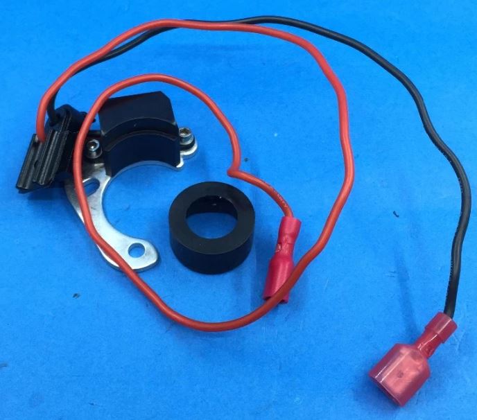
Other than the kits mentioned above, We Torque Induction have developed A superior-quality Transistor Ignition kit using High-end latest IGBT parts. Fitting is easy as Plug and Play, you don’t need to change any parts, just remove the CB system and install the single plate and you are done.

two stroke modification

Modification Of An Engine

ENGINE

When we talk about any engine mods, the first thing that comes to mind is “porting”. Well, porting is something that I guess is more of a lingo with not only RD owners, but the owners of most of the 100cc bikes around. Many bike owner is lured into the trap of mechanics who claim to boost power by porting their barrels, well I for one have been a victim too. Most or maybe all the mechanics I have been to, barring one, know zilch about porting. So giving your barrels to them could as well be farewell…!!
Well in this space, I will try and share with you all the mods I have tried out on my bike. I really feel that anyone who wants to carry out these do-it-yourself mods should either have plenty of backup spares or have a parts bike so that even if anything goes wrong, you can always revert to the stock arrangement.
I have learned most of this stuff from reading and by keeping in touch with some great guys like Ron Chinoy and my mechanic John from whom I have not only learned a lot, but have been inspired to try out my own stuff.

CYLINDER HEAD MOD

Milling the gasket layer on the heads is a good way to get more power, though you’ll probably want to get someone that knows what they’re doing to do it. Basically, you want to get the piston to come very close to the flatter part of the heads (the squish band) to push the mixture to the center for a more centralized burn. This is a sure-shot way to achieve more power as it contributes to a considerable increase in the compression ratio.
However, I would suggest this mod mostly on the Indian LTs, the reason being, the huge step which was provided on the gasket layer which caused a considerable drop in compression. This was one amongst the many differences between the HTs and the LTs which were launched in India. While the HTs had a step of 1mm on the gasket layer, the LTs had a step of about 2.5mm. Milling this down to 1mm should be good enough.
However, remember one thing, if you get too radical with this, especially on the LTs, there is a good chance that you may very well burn a hole in your piston. Radical milling should be accompanied by advancing the outlets to compensate for the raised compression.
Cylinder heads can be reshaped to change the power band. Generally speaking, a cylinder head with a small diameter and deep combustion chamber, and a wide squish band (60% of the bore area). Combined with a compression ratio of 9 to 1 is ideally suited for low to mid-range power. A cylinder head with a wide shallow chamber and a narrow squish band (35-45% of bore area) and a compression ratio of 8 to 1, is ideally suited for high rpm power.
There are many reasons why a particular head design works for certain types of racing. For example; a head with a wide squish band and a high compression ratio will generate high turbulence in the combustion chamber. This turbulence is termed Maximum Squish Velocity, MSV is rated in meters per second (m/s).

PORTING

The process of cylinder porting is a funny paradox. The people in the market to buy it are looking for information and the people in the market of selling it are hiding information on porting. So much myth and misinformation is associated with this complex machining and metal finishing process. Yet the tooling is easily available and the design of the ports is actually quite straightforward with resources like computer design programs. This article is an overview of how porting is performed and how it can benefit your performance demands.

Two-Stroke Principles::.
Although a two-stroke engine has fewer moving parts than a four-stroke engine, a two-stroke is a complex engine with different phases taking place in the crankcase and in the cylinder bore at the same time. This is necessary because a two-stroke engine completes a power cycle in only 360 degrees of crankshaft rotation, compared to a four-stroke engine, which requires 720 degrees of crankshaft rotation to complete one power cycle. Two-stroke engines aren’t as efficient as four-stroke engines, meaning that they don’t retain as much air as they draw in through the intake. Some of the air is lost out of the exhaust pipe. If a two-stroke engine could retain the same percentage of air, it would be twice as powerful as a four-stroke engine because they produce twice as many power strokes in the same number of crankshaft revolutions. The following is an explanation of the basic operation of the two-stroke engine.

1. Starting with the piston at the top dead center (TDC 0 degrees) ignition has occurred and the gasses in the combustion chamber are expanding and pushing down the piston. This pressurizes the crankcase causing the reed valve to close. At about 90 degrees after TDC the exhaust port opens ending the power stroke. A pressure wave of hot expanding gasses flows down the exhaust pipe. The blow-down phase has started and will end when the transfer ports open. The pressure in the cylinder must blow down to below the pressure in the crankcase in order for the unburned mixture gasses to flow out the transfer ports during the scavenging phase.

2. Now the transfer ports are uncovered at about 120 degrees after TDC. The scavenging phase has begun. Meaning that the unburned mixture gasses are flowing out of the transfers and merging together to form a loop. The gasses travel up the backside of the cylinder and loops around in the cylinder head to scavenge out the burnt mixture gasses from the previous power stroke. It is critical that the burnt gasses are scavenged from the combustion chamber, to make room for as much unburned gasses as possible. That is the key to making more power in a two-stroke engine. The more unburned gasses you can squeeze into the combustion chamber, the more the engine will produce. Now the loop of unburned mixture gasses has traveled into the exhaust pipe’s header section. Most of the gasses aren’t lost because a compression pressure wave has reflected from the baffle cone of the exhaust pipe, to pack the unburned gasses back into the cylinder before the piston closes off the exhaust port.

3. Now the crankshaft has rotated past the bottom dead center (BDC 180 degrees) and the piston is on the upstroke. The compression wave reflected from the exhaust pipe is packing the unburned gasses back in through the exhaust port as the piston closes off the port the start the compression phase. In the crankcase, the pressure is below atmospheric producing a vacuum and a fresh charge of unburned mixture gasses are flowing through the reed valve into the crankcase.

4. The unburned mixture gasses are compressed and just before the piston reaches TDC, the ignition system discharges a spark causing the gasses to ignite and start the process all over again.

What is Porting::.

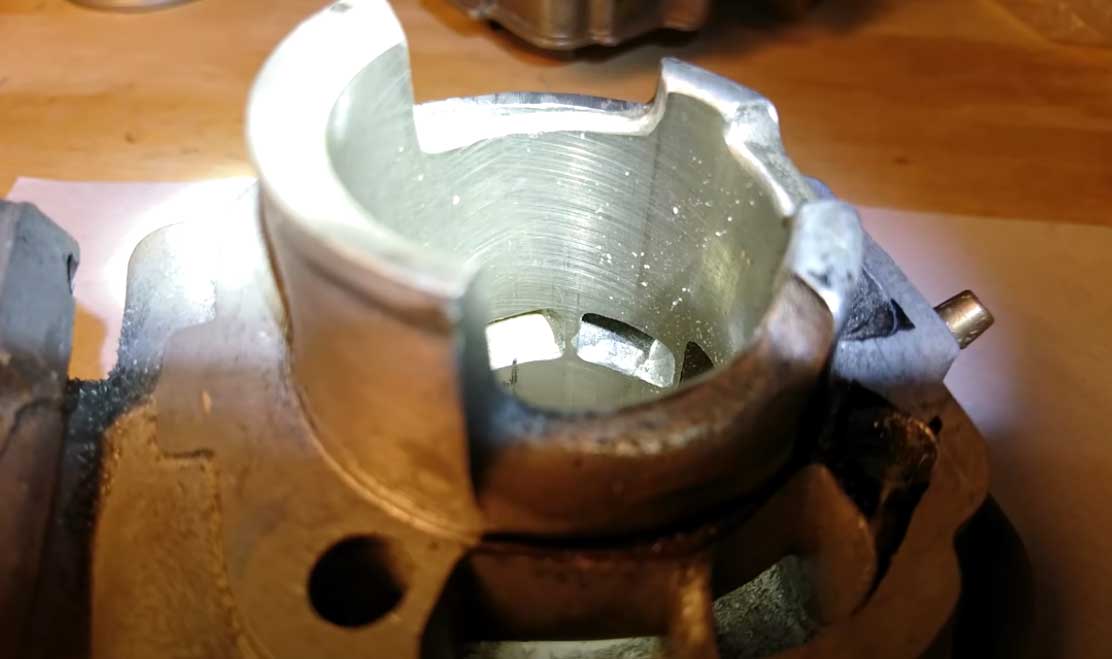
Porting is a metal finishing process performed to the passageways of a two-stroke cylinder and crankcases, that serves to match the surface texture, shapes, and sizes of port ducts, and the timing and angle aspects of the port windows that interface with the cylinder bore. The port windows determine the opening and closing timing of the intake, exhaust, blowdown, and transfer phases that take place in the cylinder. These phases must be coordinated to work with other engine components such as the intake and exhaust systems. The intake and exhaust systems are designed to take advantage of the finite amplitude waves that travel back and forth from the atmosphere. Porting coordinates the opening of the intake, exhaust, and transfer ports to maximize the tuning affect of the exhaust pipe and intake system. Generally speaking, porting for more mid-range acceleration is intended for use with stock intake and exhaust systems.

Terminology::.
These are some common words and terms associated with porting.

Ports::.
Passageways are cast and machined into the cylinder.

Ducts::.
The tube shape that comprises the ports.

Windows::.
The part of the port that interfaces the cylinder bore.

ExhaustPort::.
The large port where the burnt gasses exit the cylinder.

ExhaustBridge::.
The center divider is used on triangular-shaped exhaust ports.

Sub-ExhaustPorts::.
The minor exhaust ports are positioned on each side of the main exhaust port.

Sub-ExhaustPorts::.TriplePorts::.
One main bridgeless exhaust port with one sub-exhaust port on each side.

FrontTransfers::.
Transfer ports link the crankcase to the cylinder bore. The front set (2) of transfers is located closest to the exhaust port.

RearTransfers::.
The rear set of transfers is located closest to the intake port.

AuxiliaryTransfers::.
Some cylinders have a minor set of transfers located between the front and rear sets.

TransferPortAreaRatio::.
The area of the crankcase side of the transfers divided by the area of the port window.

BoostPorts::.
The port or ports that are located opposite of the exhaust port and in line with the intake port. These ports are usually by-pass ports for the intake or piston and sharply angled upwards to help direct the gas flow during scavenging.

Port-Time-Area::.
A mathematical computation of the area of a port, divided by the displacement of the cylinder and multiplied by the time that the port is open. The higher an engine revs the more time area the port needs. The higher the piston speed the less time is available for the gas to flow through the port.

Duration::.
The number of crankshaft angle rotational degrees that a port is open.


The crank angle degree when the piston uncovers the port.

CrankAngle::.
Measured in units of degrees of crankshaft rotation. On a two-stroke engine, there are a total of 360 degrees of crankshaft rotation in one power cycle.

PortSideangle::.
The side angle of a port measured at the window, from the centerline of the bore with the exhaust port being the starting point (0).

PortRoofangle::.
The angle of the top of the port at the window.

PortHeight::.
The distance from the top of the cylinder to the opening point of the port.

TopDeadCenter (TDC)::.
The top of the piston’s stroke.

BottomDeadCenter (BDC)::.
The bottom of the piston’s stroke.

ChordalWidth::.
The effective width of a port, is measured from the straightest point between sides.
———————————————————————————————————–
BMEP::.
Brake Mean Effective Pressure.(Brake Mean Effective Pressure. Engineering Term & Method of Comparing All Engines.

BMEP-PSI = Average Cylinder Pressure in PSI

Two Stroke — BMEP = HP x 6500 / L x RPM
Four Stroke — BMEP = HP x 13000 / L x RPM

L = Displacement in Litres (80 cc = .08 Litres) (700 cc = .7 Litres)
———————————————————————————————-
Note: 3% Loss of HP & Air Density — each 1000 ft. of Elevation Above Sea Level
———————————————————————————————-

Examples: 1000 T- Cat 166 hp @ 8400 rpm
(166 hp x 6500 = 1079000) / (1 x 8400) = 128.45 BMEP
(190 hp x 6500 = 1235000) / (1 x 8400) = 147.02 BMEP

Ported T Cat ~ Exhaust TA (time area) = 155.6 BMEP @ 8400 rpm
155.6 / (6500 / 8400) = 0.7738 ~ 155.6/.7738 = 201.08 hp

700 Yamaha Mtn. Max 140 hp @ 8200 rpm
(140 x 6500 = 910000) / (.7 x 8200 = 5740) = 158.53 BMEP
142 hp @ 8000 rpm (923000) / (5600) = 164.82 BMEP
150 hp @ 9000 rpm (975000 / (6300) = 154.76 BMEP

982 SRX Union Bay 211 hp @ 8900 rpm
(211 x 6500 = 1371500) / (.982 x 8900 = 8739.8) = 156.93 BMEP

A good way to compare engine volumetric efficiency. Engine compression in psi plus pipe working at 110% may? come close to BMEP. If your BMEP is not higher than your compression psi — you have a problem.

Snowmobile Guidelines: Less than 160 BMEP = 92 octane Pump Gas
Race Sleds 160 -190 BMEP = 94 octane – C16 Race Gas
———————————————————————————————————

LoopScavenging::.
Scavenging is the process of purging the combustion chamber of burnt gasses. Loop scavenging refers to the flow pattern generated by the transfer port duct shapes and port entry angles and area. The gasses are directed to merge together and travel up the intake side of the bore into the head and loop around towards the exhaust port.

Blow-Down::.
This is the time area of the exhaust port between the opening time of the exhaust and the transfers. When the exhaust port opens the pressure blows down, ideally to below the rising pressure of the gasses in the transfer ports. Blow-down is measured in degrees of crank rotation and time area.

EffectiveStroke::.
The distance from TDC to the exhaust port height. The longer the effective stroke the better the low-end power.

PrimaryCompressionRatio::.
The compression ratio of the crankcase.

SecondaryCompressionRatio::.
The compression ratio of the cylinder head.

CompressionWaves::.
Pressure waves that reflect from the end of the intake or exhaust system and return to the engine.

ExpansionWaves::.
Pressure waves travel from the engine and out to the atmosphere.

ToolsoftheTrade::.
There are two main types of tools used in porting, measuring, and grinding. Here is an overview of how these tools are used.

Measuring::.
The basic measuring tools include a dial caliper, an inside divider, and an assortment of angle gauges. The caliper is used to measure the port height, the divider is used to measure the chordal width of the port, and the angle gauges are used to measure the roof and side angles of the ports. Calipers and dividers are available from places like Sears or industrial supply stores. Angle gauges are fashioned from cardboard and specific to individual cylinders.

Grinding::.
The most common grinding tools are electric-powered. They consist of a motor, speed control, flexible drive shaft, tool handle, and tool bits. The power of these motors ranges from 1/5th to 1/4th HP with a maximum rpm of 15,000.
The tool handles and bits are the secrets to porting. There are two types of tool handles; straight and right angle. The straight tool handles are used for machining the port ducts. The right-angle tool handles are used to gain access to the port windows from the cylinder bore. Over the years I’ve tested hundreds of different tool bits and arrived at some simple materials and patterns for finishing the different surfaces of a cylinder. The materials of a cylinder range from aluminum as the base casting material, to a cast iron or steel liner, or nickel composite plated cylinder bores. Here are the basic tool bits used for porting; tungsten carbide works best for aluminum, steel, and cast iron, and stones are best for grinding through nickel composite. The tungsten carbide tool bits are available in hundreds of different patterns and shapes. The diamond pattern is the best performing and the shape of the bit should match the corresponding shape of the port. Stones, or mounted points as they are termed in industrial supply catalogs, are available in different shapes and grits. The grits are graded by the color of the stones. Gray being the most course and red being the finest. The finer the grit the faster it wears but the smoother the finish.

MakingPortsBigger::.
Generally speaking, if you’re trying to raise the peak rpm of the powerband with an aftermarket exhaust system of clutching on a snowmobile, the ports will probably need to be machined in this manner; widen the transfer ports for more time area and raise the exhaust port for more duration. Most OEM cylinders have exhaust ports that are cast to the maximum safe limit of chordal width. Often times widening the exhaust port will cause accelerated piston and ring wear. In some cases, the port will be widened so far that it breaks through into the water jacket. The internal casting on some cylinders is so thin that it prevents tuners from widening the exhaust port.
Transfer ports should be widened with respect to the piston ring centering pins. The ports should have a safe margin of 2mm for the centering pin. The height of the transfer ports is based on the time area of the exhaust port above the transfer port opening height. That is called Blow-down. The exhaust port has to evacuate the cylinder bore of burnt gasses before the transfers open, otherwise, backflow will occur into the crankcase. That can cause a variety of dangerous problems like blown crank seals, chipped or burnt reeds, or in extreme circumstances a fire that can extend out of the carb. The angles of the transfers are important too. Generally speaking when the side angles direct the gasses to the intake side of the cylinder, or the roof angles are steep angle 15-25 degrees), the porting will be better for trail-riding. When the side angles direct the gasses to the center of the cylinder and the roof angles are nearly flat (0-5 degrees), the porting will be better suited to drag or lake racing.

MakingPortsSmaller::.
Ports are purposely made smaller for several reasons. One or more of the ports could have been designed too big, or a well-meaning tuner may have been overzealous, or a customer may have asked for more than he could handle. There are performance gains to be had from smaller ports, for high altitude compensation or for more punch for trail and snowcross riding. Simply using a thinner base gasket or by turning down the cylinder base on a lathe. Cometic Gasket Co. in Mentor Ohio makes graded gaskets from .25 to 1.5mm and even custom base plates for stroker engines. (www.cometic.com) Another method is by welding the perimeter of the port, although that entails re-plating the bore. Transfer and intake ports can be made smaller with the use of epoxy. Brand name products like DURO Master Mend or Weld-Stick are chemical resistant, easy to mold to fit, and can withstand temperatures of 400F. Master Mend is a liquid product and Weld-Stick is a semi-dry putty material. The epoxy can be applied to the roof of the ports to retard the timing and reduce the duration. It can be applied to the sides of the transfers to reduce the time area, and it can be applied to the transfer ducts to boost the primary compression ratio (crankcase volume).

difference between torque and horsepower

Torque And Horsepower.

BY BRUCE AUGENSTEIN

There’s been a certain amount of discussion, in this and other files, about the concepts of horsepower and torque, how they relate to each other, and how they apply in terms of automobile performance. I have observed that, although nearly everyone participating has a passion for automobiles, there is a huge variance in knowledge. It’s clear that a bunch of folks have strong opinions (about this topic, and other things), but that has generally led to more heat than light if you get my drift :-). I’ve posted a subset of this note in another string but felt it deserved to be dealt with as a separate topic. This is meant to be a primer on the subject, which may lead to a serious discussion that fleshes out this and other subtopics that will inevitably need to be addressed. OK. Here’s the deal, in moderately plain English.

Force, Work, and Time

If you have a one-pound weight bolted to the floor, and try to lift it with one pound of force (or 10, or 50 pounds), you will have applied force and exerted energy, but no work will have been done. If you unbolt the weight and apply a force sufficient to lift the weight one foot, then a one-foot pound of work will have been done. If that event takes a minute to accomplish, then you will be doing work at the rate of a one-foot pound per minute. If it takes one second to accomplish the task, then work will be done at the rate of 60 foot-pounds per minute, and so on.
In order to apply these measurements to automobiles and their performance (whether you’re speaking of torque, horsepower, newton meters, watts, or any other terms), you need to address the three variables of force, work, and time.
A while back, a gentleman by the name of Watt (the same gent who did all that neat stuff with steam engines) made some observations and concluded that the average horse of the time could lift a 550-pound weight one foot in one second, thereby performing work at the rate of 550-foot pounds per second, or 33,000-foot pounds per minute, for an eight-hour shift, more or less. He then published those observations and stated that 33,000-foot pounds per minute of work were equivalent to the power of one horse, or, one horsepower.

Everybody else said OK. 🙂

For purposes of this discussion, we need to measure units of force from rotating objects such as crankshafts, so we’ll use terms that define a *twisting* force, such as foot-pounds of torque. A foot pound of torque is the twisting force necessary to support a one-pound weight on a weightless horizontal bar, one foot from the fulcrum.
Now, it’s important to understand that nobody on the planet ever actually measures horsepower from a running engine. What we actually measure (on a dynamometer) is torque, expressed in foot pounds (in the U.S.), and then we *calculate* actual horsepower by converting the twisting force of torque into the work units of horsepower.
Visualize that one-pound weight we mentioned, one foot from the fulcrum on its weightless bar. If we rotate that weight for one full revolution against a one-pound resistance, we have moved it a total of 6.2832 feet (Pi * a two-foot circle), and, incidentally, we have done 6.2832 foot pounds of work.
OK. Remember Watt? He said that 33,000 foot pounds of work per minute was equivalent to one horsepower. If we divide the 6.2832 foot pounds of work we’ve done per revolution of that weight into 33,000 foot pounds, we come up with the fact that one foot pound of torque at 5252 rpm is equal to 33,000 foot pounds per minute of work, and is the equivalent of one horsepower. If we only move that weight at the rate of 2626 rpm, it’s the equivalent of 1/2 horsepower (16,500 foot pounds per minute), and so on. Therefore, the following formula applies for calculating horsepower from a torque measurement:

Torque * RPM

Horsepower = ————5252

This is not a debatable item. It’s the way it’s done. Period.
The Case For Torque
Now, what does all this mean in Carland?
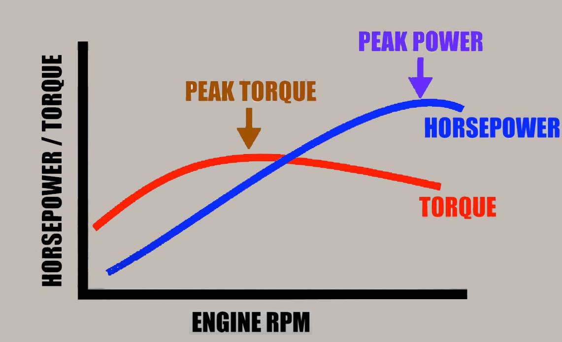
First of all, from a driver’s perspective, torque, to use the vernacular, RULES :-). Any given car, in any given gear, will accelerate at a rate that *exactly* matches its torque curve (allowing for increased air and rolling resistance as speeds climb). Another way of saying this is that a car will accelerate hardest at its torque peak in any given gear, and will not accelerate as hard below that peak, or above it. Torque is the only thing that a driver feels, and horsepower is just sort of an esoteric measurement in that context. 300 foot pounds of torque will accelerate you just as hard at 2000 rpm as it would if you were making that torque at 4000 rpm in the same gear, yet, per the formula, the horsepower would be *double* at 4000 rpm. Therefore, horsepower isn’t particularly meaningful from a driver’s perspective, and the two numbers only get friendly at 5252 rpm, where horsepower and torque always come out the same.

In contrast to a torque curve (and the matching pushback into your seat), horsepower rises rapidly with rpm, especially when torque values are also climbing. Horsepower will continue to climb, however, until well past the torque peak, and will continue to rise as engine speed climbs, until the torque curve really begins to plummet, faster than engine rpm is rising. However, as I said, horsepower has nothing to do with what a driver *feels*.

You don’t believe all this?

Fine. Take your non-turbo car (turbo lag muddles the results) to its torque peak in first gear, and punch it. Notice the belt in the back? Now take it to the power peak, and punch it. Notice that the belt in the back is a bit weaker. Fine. Can we go on, now? 🙂

The Case For Horsepower
OK. If torque is so all-fired important, why do we care about horsepower?
Because (to quote a friend), “It is better to make torque at high rpm than at low rpm, because you can take advantage of *gearing*.

For an extreme example of this, I’ll leave Carland for a moment, and describe a waterwheel I got to watch a while ago. This was a pretty massive wheel (built a couple of hundred years ago), rotating lazily on a shaft that was connected to the works inside a flour mill. Working some things out from what the people in the mill said, I was able to determine that the wheel typically generated about 2600(!) foot pounds of torque. I clocked its speed and determined that it was rotating at about 12 rpm. If we hooked that wheel to, say, the drive wheels of a car, that car would go from zero to twelve rpm in a flash, and the waterwheel would hardly notice :-).
On the other hand, twelve rpm of the drivewheels is around one mph for the average car, and, in order to go faster, we’d need to gear it up. Getting to 60 mph would require gearing the wheel up enough so that it would be effectively making a little over 43 foot pounds of torque at the output, which is not only a relatively small amount, it’s less than what the average car would need in order to actually get to 60. Applying the conversion formula gives us the facts on this. Twelve times twenty-six hundred, over five thousand two hundred fifty-two gives us:

6 HP.

Oops. Now we see the rest of the story. While it’s clearly true that the water wheel can exert a *bunch* of force, its *power* (ability to do work over time) is severely limited.

At The Dragstrip
OK. Back to Carland, and some examples of how horsepower makes a major difference in how fast a car can accelerate, in spite of what torque on your backside tells you :-).
A very good example would be to compare the current LT1 Corvette with the last of the L98 Vettes, built-in 1991. Figures as follows:

Engine Peak HP @ RPM Peak Torque @ RPM

—— ————- —————–

L98 250 @ 4000 340 @ 3200
LT1 300 @ 5000 340 @ 3600

The cars are geared identically, and car weights are within a few pounds, so it’s a good comparison.
First, each car will push you back in the seat (the fun factor) with the same authority – at least at or near peak torque in each gear. One will tend to *feel* about as fast as the other to the driver, but the LT1 will actually be significantly faster than the L98, even though it won’t pull any harder. If we mess about with the formula, we can begin to discover exactly *why* the LT1 is faster. Here’s another slice at that formula:

Horsepower * 5252

Torque = —————–RPM

If we plug some numbers in, we can see that the L98 is making 328 foot pounds of torque at its power peak (250 hp @ 4000), and we can infer that it cannot be making any more than 263 pound feet of torque at 5000 rpm, or it would be making more than 250 hp at that engine speed and would be so rated. In actuality, the L98 is probably making no more than around 210 pound feet or so at 5000 rpm, and anybody who owns one would shift it at around 46-4700 rpm, because more torque is available at the drive wheels in the next gear at that point. On the other hand, the LT1 is fairly happy making 315 pound-feet at 5000 rpm and is happy right up to its mid-5s redline.

So, in a drag race, the cars would launch more or less together. The L98 might have a slight advantage due to its peak torque occurring a little earlier in the rev range, but that is debatable since the LT1 has a wider, flatter curve (again pretty much by definition, looking at the figures). From somewhere in the mid-range and up, however, the LT1 would begin to pull away. Where the L98 has to shift to second (and throw away torque multiplication for speed), the LT1 still has around another 1000 rpm to go in first, and thus begins to widen its lead, more and more as the speeds climb. As long as the revs are high, the LT1, by definition, has an advantage.

Another example would be the LT1 against the ZR-1. Same deal, only in reverse. The ZR-1 actually pulls a little harder than the LT1, although its torque advantage is softened somewhat by its extra weight. The real advantage, however, is that the ZR-1 has another 1500 rpm in hand at the point where the LT1 has to shift.

There are numerous examples of this phenomenon. The Integra GS-R, for instance, is faster than the garden variety Integra, not because it pulls particularly harder (it doesn’t), but because it pulls *longer*. It doesn’t feel particularly faster, but it is.
A final example of this requires your imagination. Figure that we can tweak an LT1 engine so that it still makes peak torque of 340 foot pounds at 3600 rpm, but, instead of the curve dropping off to 315 pound feet at 5000, we extend the torque curve so much that it doesn’t fall off to 315 pound feet until 15000 rpm. OK, so we’d need to have virtually all the moving parts made out of unobtanium :-), and some sort of turbocharging on demand that would make enough high-rpm boost to keep the curve from falling, but hey, bear with me.

If you raced a stock LT1 with this car, they would launch together, but, somewhere around the 60 foot point, the stocker would begin to fade, and would have to grab second gear shortly thereafter. Not long after that, you’d see in your mirror that the stocker has grabbed third, and not too long after that, it would get fourth, but you wouldn’t be able to see that due to the distance between you as you crossed the line, *still in first gear*, and pulling like crazy.

I’ve got a computer simulation that models an LT1 Vette in a quarter-mile pass, and it predicts a 13.38 second ET, at 104.5 mph. That’s pretty close (actually a tiny bit conservative) to what a stock LT1 can do at 100% air density at a high traction drag strip, being powershifted. However, our modified car, while belting the driver in the back no harder than the stocker (at peak torque) does an 11.96, at 135.1 mph, all in first gear, of course. It doesn’t pull any harder, but it sure as hell pulls longer :-). It’s also making *900* hp, at 15,000 rpm.
Of course, folks who are knowledgeable about drag racing are now openly snickering, because they’ve read the preceding paragraph, and it occurs to them that any self-respecting car that can get to 135 mph in a quarter mile will just naturally be doing this in less than ten seconds. Of course, that’s true, but I remind these same folks that any self-respecting engine that propels a Vette into the nines is also making a whole bunch more than 340 foot pounds of torque.

That does bring up another point, though. Essentially, a more “real” Corvette running 135 mph in a quarter mile (maybe a mega big block) might be making 700-800 foot-pounds of torque, and thus it would pull a whole bunch harder than my paper tiger would. It would need slicks and other modifications in order to turn that torque into forwarding motion, but it would also get from here to way over there a bunch quicker.
On the other hand, as long as we’re making quarter-mile passes with fantasy engines, if we put a 10.35:1 final-drive gear (3.45 is stock) in our fantasy LT1, with slicks and other chassis mods, we’d be in the nines just as easily as the big block would, and thus save face :-). The mechanical advantage of such a nonsensical rear gear would allow our combination to pull just as hard as the big block, plus we’d get to do all that gear banging and such that real racers do and finish in fourth gear, as God intends. 🙂

The only modification to the preceding paragraph would be the polar moments of inertia (flywheel effect) argument brought about by such a stiff rear gear, and that argument is outside of the scope of this already massive document. Another time, maybe, if you can stand it :-).

At The Bonneville Salt Flats
Looking at top speed, horsepower wins again, in the sense that making more torque at high rpm means you can use a stiffer gear for any given car speed, and thus have more effective torque *at the drive wheels*.
Finally, operating at the power peak means you are doing the absolute best you can at any given car speed, measuring torque at the drive wheels. I know I said that acceleration follows the torque curve in any given gear, but if you factor in gearing vs car speed, the power peak is *it*. An example, yet again, of the LT1 Vette will illustrate this. If you take it up to its torque peak (3600 rpm) in a gear, it will generate some level of torque (340 foot pounds times whatever overall gearing) at the drive wheels, which is the best it will do in that gear (meaning, that’s where it is pulling hardest in that gear).

However, if you re-gear the car so it is operating at the power peak (5000 rpm) *at the same car speed*, it will deliver more torque to the drive wheels, because you’ll need to gear it up by nearly 39% (5000/3600), while engine torque has only dropped by a little over 7% (315/340). You’ll get a 29% gain in drive wheel torque at the power peak vs the torque peak, at a given car speed.
Any other rpm (other than the power peak) at a given car speed will net you a lower torque value at the drive wheels. This would be true of any car on the planet, so, the theoretical “best” top speed will always occur when a given vehicle is operating at its power peak.

“Modernizing” The 18th Century
OK. For the final-final point (Really. I Promise.), what if we ditched that water wheel, and bolted an LT1 in its place? Now, no LT1 is going to be making over 2600 foot-pounds of torque (except possibly for a single, glorious instant, running on nitromethane), but, assuming we needed 12 rpm for input to the mill, we could run the LT1 at 5000 rpm (where it’s making 315 foot pounds of torque), and gear it down to a 12 rpm output. Result? We’d have over *131,000* foot pounds of torque to play with. We could probably twist the whole flour mill around the input shaft if we needed to :-).

The Only Thing You Really Need to Know
Repeat after me. “It is better to make torque at high rpm than at low rpm because you can take advantage of *gearing*.” 🙂 Thanks for your time.

more power to rd yamaha

More Power To Air Cooled RD

BY DAVID FREIST

All Credit goes to the real Author of the article.

Introduction

When I first started out trying to get more power out of my stock RD I relied on the experience I had with my first RD-350, a ’73 #101439. That bike ended up with Bassani chambers, a swiss-cheesed airbox, and slightly re-jetted carbs: mains up to 160. That’s it. I rode it that way for a year and a half, then traded it in on a new Kawasaki H1. At that time I didn’t know a damn thing about tuning a 2-stroke engine.
I bought my current RD in July, ’79 and have had it off and on ever since. It had 101 miles on it when I got it (yep! In ’79!) and has almost 13,000 on it now. My daughter had it for several years, storing it out in the Pacific Northwest weather, on the side stand against a fence. Not good. I got it back in 09/94 and have been fixing it up ever since, money being the limiting factor.
When I started doing the Dale A. carb mods back in ’96, I searched all over for those fabled 5J9 needles to fit his specifications. However, the pair I finally did locate came with a caution that they probably would be too rich in the mid-range. How True! The bike was almost unrideable in the mid-range. All the fiddling with jetting combinations that I could try or be recommended did not work. Phone calls to Dale just got a scratch on his head and a sympathetic, “You’ll get it right, it worked on mine…” Later discussions focused on application and it was concluded that the 5J9 needle was just too rich in the mid-range for a stock-ported engine. So now what? As far as I was concerned I was stuck in la-la land without a needle…so time to hit the books. I finally discovered that the Dale A. carb mod re-jet was simply a retrofit to parts from the ’72 R5C 350, but it used 5DP7 needles. I bought a pair and the equation was finally (almost) solved.
In the last four years, I have learned how to make my stock ’75 RD-350 perform much better without having to disassemble the engine. In this article I will give a little background on my bike, why and how I did the modifications I will describe, and their results. These modifications work for both the air-cooled RD-350 and the RD-400.
I bought my RD-350 in 1979 with 101 miles on the odometer. I gave it away in ’76 and bought it back for $350 in ’94; it was in bad shape. I fixed it up the best I could, got it running, and found out about the 2-Stroke list. There I met Dale Alexander. Dale is what properly is properly termed, a “Guru” for the RD. Because of articles he had written about getting more performance from these machines, I decided to try some of them out. At this point, I should say that I had already made a few modifications for more power. I drilled the air box full of holes for more flow and installed a set of DG expansion chambers. With these changes I had to re-jet the carburetors, changing the main jets from size 105 to size 160. This alone will make an RD much quicker and faster. I wanted more, my appetite was whetted by Dale’s articles. The updated pieces can be found at Mike Hammer’s website, or at Doug Johnson’s, www.motocarerra.com. I decided to modify my carburetors per Dale’s specifications and change to a single tall air filter mounted directly onto the stock intake runner, removing the air box in the process. This proved to be a much bigger task than I ever imagined. More than a few times I had the urge to push the damn thing over the cliff at the end of my street, trying in vain to get the jetting right…but that’s another story.
This article assumes you already have expansion chambers. It doesn’t really matter what brand. The modifications can be done on a bike with stock pipes, and it works very well. The later mods helped me get rid of the characteristic rich spot in the powerband, induced by out-of-phase positive and negative pressure waves reflecting back and forth through the engine by the expansion chambers. Let’s list what parts are necessary to convert your RD carbs to get smoother, more responsive power. They are:

RD-350:

2 169-P0 or -P2 needle jets
2 5DP7 needles
Several pairs of main jets, ranging from 180-220
2 2mm air jets
1 K&N air filter, part #RD-0710


RD-400

Same as above, except the air filter and necessary intake runner can be bought as a kit from ProFlo, MotoCarerra, SpecII, and a few others. The carb parts can be purchased from the same places or direct from Sudco-Mikuni. All these suppliers have websites.
You’ll also need a drill motor, a #30 drill bit, and a 4mm tap if you want adjustable air jets. If you just want to go with the 2mm, a 5/64th drill bit will do the job.
Completely disassemble one carb. Drill out the old air jet. It’s located in the carb passage at 6 o’clock on the upstream side of the carb. A sharp #30 drill bit will bite and spin the jet, then it will come right out. On the 400, the brass dome covering the passage needs removal before you can get the old air jet out. I use a sharp punch to dimple the dome. This might push the dome further into the passage, but the sucker is coming out anyway. Drill a small hole in the dome, then insert a screw. Use a pair of pliers and pry out the dome. Then drill out the air jet. On the 350 it’ll spin out with the bit. On the 400 it’ll usually fall right out after being spun a few times. Stop here.
If you want adjustable air jets, drill out the rest of the passage with the #30 drill bit. Then tap the hole with the 4mm tap, Be careful; when the tap starts to get tight, run it back out and blow out the chips. You don’t want to break off a tap! When you can just see the tip of the tap coming out the hole into the needle jet passage, stop. This provides a positive stop for the new 2mm air jet, which you now install in the drilled and tapped passage. Reassemble the carb with the new needle jet, needle and start with the 220 main jet. Do the same thing to the other carb.
If you just want the 2mm passage (the above procedure can be done at another time), just finish drilling out the passage with the 5/64th drill and reassemble the carb as above. Then do the same thing to the other carb.
If you are still using them, ditch the old airbox and air filter. Otherwise, install the carbs, intake Y, and new air filter. Set the air screws at 1 turn out. Start it up and ride it. If it wants to buck and hesitate on deceleration, turn the air screws in 1/8th at a time until it’s smooth. If this doesn’t work, install the next size-up pilot jet, a #27.5, or even a #30, then readjust the air screws at 1-1/2 turns out and fine-tune from there. The main jets at 220 will be rich, but not too much. I’m currently running #200 mains.
These mods will give more power, a smoother powerband, and spread out the big hit at 6K on a stock-carbureted RD. You also get a tiny rich spot if you are running expansion chambers. I got rid of that.

RECENT ADDITIONS

Recently I added a few more bolt-on performance improvements, which incidentally removed the rich spot I had a 5.5K. Those parts were:

RZ intake manifolds modified to fit ported RD reed cages
A homemade balance tube for the manifolds (the RZ tube will work)
TDR single-petal fiberglass reeds

These improvements banished the characteristic mid-range richness caused by expansion chambers, and also an added increase in power. To my surprise, no jetting changes were required.
Finally, I have changed the balance tube for a White Bros. Boost bottle (meant for a Banshee) and Hinson 3/8″ reed spacers (also for the Banshee). The boost bottle adds mid-range power and smooths out the power even more than before. The spacers move the cages back, unshrouding the boost port and adding some crankcase volume. More low-end torque as a result. The latest addition is a pair of gorgeous DG gold-anodized heads, which closed up the squish clearance and raised compression

ART OF SQUISHING

BY DALE ALEXANDER

In the past couple of issues, Doug has been doing a credible job of explaining heat, race fuel, and the likes. I’ve enjoyed what I’ve read and this has compelled me to add my two cents based on my past racing experience with RD-350’s.
When I started racing RD’s, the fast guys on the west coast were Alan and Dain Gingerelli, Dick Fuller, Scott Clough and Bob Tigert. They were fast at tracks like Sears Point, Riverside, and Ontario. I was just a wee pup of eighteen and had a lot to learn. By the time I left racing, it took Yamaha’s then-latest creation, the FZR 400, to make my fifteen-year-old RD-375 obsolete. What I mean by obsolete was that I had been relegated to finishing 7th with six FZR 400’s in front of me. Not wishing to spend $5000 to ”purchase’ trophies, I hung it up. What’s important here is the fact that I would very much like to pass on the knowledge that I have accumulated during all those years and as Doug has more or less started the ball rolling with his articles on heat, I see no reason to break stride.

Stone Knives and Bear Claws

Way back when Mt. Everest was a foothill and two-strokes only came in one, two or three cylinders, companies like Denco Engineering and Hot Bike Engineering were running Kawasaki triples regularly at Fremont Dragstrip. Tony Nicosia would run the Kaws all the way down to the end on the back wheel, severely stressing the wheelie bars. Quite a sight to behold. And when the bikes were brought back to the pre-staging area, a curious ritual would begin. Out came the pressurized water sprayers to hose the cylinders, heads, and cases off. Some wise-ass would invariably make a comment like ‘It doesn’t matter how much they water them things, they ain’t gonna grow any faster.
My own experience with road racing was just beginning to develop. I was soon to observe that the RD would run pretty strong in 6th gear out of one corner, only to be reduced to 5th gear and finally 4th gear by the end of the race. The engine was consistently losing power as the race progressed. Something was overheating, BUT WHAT? Suzuki had Ram-Air heads on their 380 and 550 triples, after-market water-cooled heads were available but even the factory water pumpers were having a like problem so what was the point?
To make matters really confusing, all manner of porting ideas were being tried, but everyone was going pretty much the same speed or slower. So it would seem that whatever the problem was, it was related to heat, the development of power, and the amount of time that the power was being used.

So, What IS Going On?

At this time, in the mid to late 70’s, the state of the art for porting and compression was pretty much in its infancy. Raise the exhaust port to 28 m.m., trim .020″ off the head, add some richer jetting, and let’s go racin’. This yielded a moderate increase in power and compression which, if checked by a gauge, was about 150 p.s.i.. As my quest for knowledge grew and my desire to extract reliable power increased, I started looking down other avenues to expand my understanding of what was needed to make heaps and heaps of consistent power. A not-so-obvious place to look turned out to be car racing. Even though one might at first think the four-stroke engines have little in common with two-strokes, I was soon to prove myself wrong. With the exception of how gases move in and out of cylinders, both designs are plagued with much the same problems, and the first lesson I learned about heat and how to control it led me to investigate quench bands or squish bands as they are known to us.
The squish band is the area along the outside edge of the head that is more or less flat or matches the angle of the crown of the piston closely. Its purpose is two fold: 1) it acts to create a mixing of the charge as it is compressed by the piston. This helps to make a more homogeneous mixture that burns faster with less ignition advance. And 2) when properly set up, the squish band acts to cool the charge and the end gases to help eliminate detonation. This is the really important aspect of the squish band as it relates to a two-stroke.
It acts to cool the charge. Weren’t we just wondering where all this damaging heat was coming from? I’ve looked at a ton of pistons and noted early on that a lot about heat can be learned by turning the piston upside down and looking at the area under the crown on the inside of the piston. Good running bikes had a very light brown color that was glossy. Better running bikes had a much larger area that covered the entire underside of the crown and was much darker in color, but still glossy. On bikes that didn’t run that hard, this area had turned flat black.
This is perhaps one of the best areas to keep an eye on the heat health of an engine, so it’s important to understand what information has been given to us here. Oil, whether in a four-stroke or two-stroke, is being churned up by the crankshaft and is being thrown against the underside of the piston crown. The heat of combustion moves from the chamber side of the piston crown to the underside as the piston tries to rid itself of the heat before melting. It is the presence of this heat that bakes (or burns) the oil onto the underside of the piston. A little heat, a small light-colored area. Too much heat and the oil burns carbon black. A very useful indicator indeed.
But a function of the heat that is unique to a two-stroke is that the worst of its effects is yet to be felt. When gases are heated they expand, and if the container that they are expanding into happens to be sealed, pressure rises. Well, isn’t the crankcase of a two-stroke sealed for the time needed to build pressure to start the scavenging cycle? Yes and here’s the rub. As the piston crown grows hotter, the underside radiates this heat into the crankcase, increasing the pressure to such an extent that when the intake port opens, the pressure inside the case is momentarily higher than that of the incoming charge, and everything stalls for a brief moment: brief for all things but the engine. It WILL NOT fully charge the case and as a result, the next scavenge event will not fully charge the combustion chamber and the engine is now not developing the power it did when things were cooler. Hence, Tony Nicasia waters his bikes to try and battle this problem externally.
What can be done to take care of this problem internally can best be summed up by understanding some of the nature of combustion and the physical properties of the engine. This would be a good time to glance at Figure 1.

 This drawing represents to the best of my memory a cross-section of an RD-350. It could be any engine actually. It should be fairly easy to make out the cylinder, head, piston, gasket, bolts, etc. The boxed-in area is the area that I wish to spend sometime talking about ’cause this is where all the problems regarding heat begin. Figure 2

is a blow-up of this area so move along and be quick about it! Along the left side of Figure 2, there is a darker area that corresponds to the head gasket. On an RD-350, the gasket is .040″; thick. The step just above the gasket represents the .020″ step that one will find in stock, unmodified head. Together, these two figures add up to a value of .060″. Keep this in mind, because these very small values will become VERY important in a moment. For future reference, this .060″ is properly known as piston/head clearance and will be called such.
Figure 3 shows an additional dark area that encircles the combustion chamber. This shaded area represents all the area of the head, piston crown, and cylinder wall that is exposed to the heat of combustion at T.D.C.. I like to call this area the “boundary cooling layer” area. Please note as well that I have given a value of 1000 degrees to this layer. For sake of argument, let’s say that the fuel gets into trouble (detonation) at any value greater than 1000 degrees. This is not the true temperature involved here, but for ease of arithmetic, let’s keep the numbers round. The real numbers aren’t important, just the concept. This boundary layer depicts the physical effect that occurs when hot gas is in proximity to a cooler object: the combustion gas is cooled by the presence of the cooler head, piston, etc. By experimentation, I feel comfortable saying that this layer is usually no thicker than .020″. As the piston has a boundary area that is .020″ thick and the head is .020″ thick as well, it doesn’t take a rocket scientist to see that the area between the two cooled surfaces is .020″ thick AND is uncooled by the boundary effect!!! This is the area where the problems with heat start. The combustible gases all the way out to the left side of this area are known as “end gases”. When the gases in the main portion of the chamber are ignited, several things happen at once: 1) the spark starts the actual chemical reaction that is combustion 2) the temperatures and pressures build quickly 3) the flame front moves rapidly away from the spark plug.
As the flame front moves to the end gas area, pressures rise quickly even though the piston is descending. At some point, the pressures and temperatures are great enough that the end gases will spontaneously ignite. This is known as detonation. When the end gases ignite in this fashion, the pressures in this area grow to tremendous values leading to piston fractures, hydraulic-type stress failure of small and big end needle roller bearings and other not-so-nice things. Detonation can be inaudible what all with the racket that the intake, exhaust, piston slap, and ring flutter can make, so damage can be occurring and pistons overheating without any warning to the rider. Assuming that the ignition is timed to a reasonable value and the octane rating of the fuel is sufficient for the use the engine is seeing, one of the only other things that can be done to reduce the possibility of detonation is to reduce the piston/head clearance to .035″. That way, the boundary cooling layers overlap and all end gases in this problem-prone area should be reduced in temperature to a level below the “auto-ignition” point. When this happens, the piston crown is no longer heated to such an extreme extent, and the charge in the crankcase is reduced in temperature reducing the pressurization and allowing a more complete filling, and the power goes up and stays longer as a result.
Looking back to Figure 3, note once again that the boundary layers are .020″ each and the clearance between the layers is .020″ as well. If one removes the step in the head which is approximately .020″, the piston/head clearance will be down to .040″ but my experience has been that .030″ to .035″ works the best. I think I’ll let you all stew on where to lose that other .005″/.010″ until the next issue. But rest assured the wait will be worthwhile as I’m just beginning to scratch the surface of go-fast stuff. See ya soon!

Where Were We?

Hi all! I Hope Christmas was good to all of you and porting tools, lathes, and mills were waiting for you under the X-mas tree.
The main points from the first article were to identify the source of heat-related power loss in a two-stroke engine, to identify the cause, to define what the squish band is and how it works, to identify what the physical effects are and how to spot them on a piston that had been in service and to propose a solution to remedy detonation and the heat that accompanies detonation. I also left you with some “homework.” In order to reap the benefits of a properly working squish band, I asked you to think of a way to remove an extra .005-.010″ after all the easy solutions had been done. Homework is now due!

More History

As we were looking for our solution at that time (1980’s), we were also experiencing head gasket leakage that was proving to be a problem to solve. We were torquing the head in several small steps, lapping the head, and any other manner of preventative maintenance that we could think of. We had the best luck coating the head gasket ring with the spray Copper Coat that one can get in an auto parts store. This was the longest-lasting solution. Even though, after 10 races or so, a tell-tale weeping of oil was found at the gasket area. The only reason that we could think of involved the design of the RD350 gasket and the fact that material had been removed from the head when it was cut to up the compression. We felt that the removal of the metal had reduced what could be called the “I beam” section of the head. This refers to the fact that if the head were to be sawed in half vertically through the head bolt holes, one would see a definite thickness to the metal. Any reduction of this material would weaken the head’s ability to resist deforming from a straight sealing surface. To make matters worse, the very design of the head gasket, although probably chosen to increase sealing pressures, was promoting the bending of the head as the bolts pull the head down away from the gasket. Think of a 12 ft. long piece of 2×4 resting on a brick and then have a person stand on either end to help get a mental picture of what was happening.

Help From Big Brother

Fortunately, a solution was already available in the form of the RD400 head gasket. Apparently, Yamaha may have noticed that the 350-style gasket was weak in this area and had updated it for the 400 series. The C-D-E series gasket was simply a .020″ sheet of copper that had a much greater surface area, encircling the head bolt holes and protruding out between the head bolts. This helped reduce the “brick and the board” problem. All that was needed to bring about this change was to lathe the top of the barrel until a smooth surface for the gasket was made and to add a couple of “pips” for what the 400 gasket uses to locate itself to the barrel. But we originally only wanted to remove .005-.010″ and the change from the 350 gasket (.040″) to the 400 gasket (.020″) reduced the squish by .020″. This was .010″ too close for comfort.
Well, now we need to put .010″ of the step we had originally removed way back when back into the head! This is the nature of experimentation. One change here adds up to two changes somewhere else. But this could be done as we already had the tool that we used to turn the heads in the first place. There is only one area to worry about that may not be so obvious: be sure that the OD of the step is great enough to accommodate the largest bore you expect to use. At the time, 65mm was the largest bore the bike would probably see, so the OD was set at 65.25-65.5 mm. The final form of this step would best be shown by figure 4.

Note that the two boundary layers we talked of in part one now overlap as represented by the darker area circled. This is what a squish band is supposed to look like. The charge that clings to the piston and head surfaces are cooled to below the auto-ignition point and the charge is being “squished” back to the center of the chamber in a turbulent, fast-burning mixture. By closing things up like this, detonation is reduced and the underside of the piston will once again begin to reflect the reduction of heat being pumped into the crankcase. Of course, if there is a reduction in heat below a useful point, couldn’t we once again up the compression to take advantage of this? Yes, but we’re getting ahead of ourselves now. The tool needed to turn the head is shown in Figure 7

, “Cylinder Head Turning Tool”.

The proper sized solder to check the squish clearance is 22 gauge, which is about .039″ thick. A dab of grease in four places on the crown of the piston is used to hold the solder in place. I like to use the four corners next to the head bolt holes. The piston should be about 10 mm down from the top and the solder should be about 15 mm long. Bolt the head onto the barrel. When everything is in place, turn the engine over with the bolt that holds the alternator rotor on. You should feel a slight drag as the solder is crushed. Remove the head and remove the solder being careful to note which piece came from what place. When you measure the solder, you may note that something is not right: The pieces that were close to the exhaust side may measure .040″ and the pieces that were close to the rear of the cylinder may measure .020″.

Now What’s Going On!?

What’s going on here? Didn’t we just go through all these flaming hoops to figure out what all had to be done to get to .030″? And now we have two DIFFERENT measurements!?
Ahhh! That was on paper and we have just stumbled onto another of the RD series’ design flaws. Put the head back on loosely and see how far it will move front to back. Quite a bit, yes? By doing this, aren’t we also moving the squish band closer/farther away from the piston? Indeed we are. What we need is some way to locate the head to the barrel and keep it centered as well. Not a problem. Look at the second tool drawing and note that it is a “Cylinder head, Centering Tool”. This tool works by locating the head in relation to the spark plug hole and the barrel. The hollow set screws are set equal to the bore size and then the head and the tool are placed into the barrel and tightened up. See Figure 6.

Now the head is centered. Use a 1/8″ “gun drill” which is simply a very long drill bit and drill down between the fins through the head and into the barrel. Don’t go more than about 5-7mm, you just need enough to hold a dowel pin. Do this twice for each head. See Figure 5.

Don’t be concerned about being exact. You don’t want to be close as this will ensure that the head is a custom fit for its barrel and it can’t be swapped accidentally with the other. A 1/8″ dowel of any type can be used as a locating dowel. Glue it to the barrels so it won’t be prone to falling into the engine when the head is removed. Bolt everything back up with the solder and NOW the clearance readings will be more consistent front to back. Adjust clearance as needed!
Well, now we’re getting into some good stuff! In the next part, I’ll introduce you to yet another tool for engine work as we are going to tackle this problem from another side. In addition, I will be getting into some ceramic coatings for cooking. Straight away, not pot roasts! Enjoy!!!

Almost finished now…

Well, we’ve got a motor now that runs better than most others out there and all that we have done is close up the squish clearances to a proper value and eliminate a bothersome head gasket leak. Is there anything else that can be done? Yes, there is an even easier method of sealing the head.
After using the RD-400 style head gasket for an extended period of time, something on the order of a season of racing (in California at the time, this was 18 to 20 races), it was found that the 400 gaskets would begin to leak too. And servicing the head/barrel/gasket was a bit of a bear as the hardened copper coat was difficult to remove. I was also racing a TZ-250D at the time and noted that the silicone rubber O-rings did a very good job of sealing the water jacket and the combustion gases on the water pumpers. The TZ-750 had the same setup only for a 66mm bore. Boy, that’s really close to the RD bore, especially if one is using 66mm pistons in the race engine. I discussed the idea of using the TZ-750 inner sealing O-ring with a friend of mine who was also racing RD’s as well. We didn’t know if the ring would stand up to the heat of an air-cooled engine but at times, the only thing one can do is just go ahead and try something. After all, what can happen? An instant seizure? Racing is full of that stuff, so no big deal.
So the decision was made to go ahead. As far as I knew at the time, no one had used an O-ring for the sealing of an RD before, so now we were in new territory. A new tool had to be devised that would hold the barrel true enough to allow the barrel to be turned on a lathe to cut an O-ring groove. 

Figure 8 shows what was used for the tool. The tool was just barely smaller in o.d. than the 64mm stock bore and could be shimmed up to match any other bore that was used for piston oversizes. The opposite end was made to be used for the 54mm bore used on RD-250’s so that any cylinder in the most popular RD sizes could be trued up. The larger step is where the cylinder rested while a “Tee” bar inserted into the transfer ports and screwed down into the tool held everything together. 

Figure 9 shows what the tool looks like installed and ready to turn the O-ring groove in the top of the barrel.
The tool could also be inserted into the top of the cylinder to first true the spigot of the barrel so that the head surface would run true when the O-ring groove was cut. The tool could also be used to true up the base gasket surface if it was really knackered. This would help to promote a good bore job as the base surface is the part of the cylinder that boring bars use to find the centerline of any hole. 

Figure 10 shows what the tool looks like installed and ready to turn the base/bottom surface or flange of the barrel.
Oh great! So now we’re going to run an O-ring and this combination will eliminate yet another gasket. But now the step in the head has to be an ADDITIONAL .020″ deep. Remember what I said about the nature of experimentation? One step forward…two back. By now, one full millimeter of the gasket has been pitched in the circular file never to be seen again and the head is beginning to pick up a sizable step in it again. Fortunately, this is not a major concern because the dowel pins are now holding the head in the proper register as never possible with a stock set-up. The O-ring groove dimensions have to be adhered to very closely as they will affect the way the O-ring performs and the best place that I can suggest to get the proper values would be any bearing house. All offer O-ring materials and because of this fact, they can help with the proper size of the groove. Just measure the TZ-750 O-ring and use a bearing house size that is as close as possible. This should do the trick nicely. One other caveat…you may have to grind your own tool bit to use. If this sounds like it may be a little over your head, take your local machinist out to lunch to soften him/her up before you ask for this favor! One last note: after setting up the engine like this, I never suffered a leak in this area or had to replace the head gasket again. Good stuff.

Now We Start To Cook

All right! The squish is good, the compression is up, the head gasket doesn’t leak, and the bike runs HARD long into a race. What ELSE can be done?
I like to mention to people that if one would like to see what the most current state of the art in engine technology is, then look to auto racing. This is true because a lot of very sharp people race against each other every weekend for a lot of money and this tends to bring the best ideas to the forefront quickly (and believe me, the best ideas out in the bike racing world are dated at least 5 years). One of these ideas in the early 80’s was Heat Barrier Coatings: Ceramics.
I learned of ceramic coatings one evening in the shop of Harry Hunt’s Racing. Roland Cushway was inspecting the top end of the shops TZ-250. Peeking over his shoulder I noticed that the crown of the new piston going in was green. When asked, Roland explained that the company that was coating their aluminum brake discs was trying out ceramic coating in hi-heat applications and that Roland was playing around with them on the pistons. He felt that they were allowing higher compression and that the engine was running harder at the end of the race. This, of course, was true as the coating was reducing the amount of heat that was passing through the piston into the case as we have previously talked about in this article. He had also observed that the coating nearest the edge of the piston was prone to cracking and he didn’t know if it was from detonation(which had become harder to read on the coated piston) or if the piston was rocking in the bore allowing the coating to contact the cylinder slightly and shock it. Ceramic coatings are very tough and difficult to machine, but they don’t stand up well to impact of any kind.
The coatings that Roland was using, as well as some of the popular coatings today, are generally .005″. This seemed like a very thin layer of material for the amount of heat it was being asked to insulate the piston from. I sent my pistons along to Roland’s company for coating. When they returned, I removed the coating from the edges of the crown as Roland had suggested in an attempt to reduce the cracking problem. I checked the squish clearance and found once again that the step in the cylinder had to be modified(here we go again!). After running the bike for a practice day, the pistons were removed and the underside inspected, and lo and behold, the dark area under the crown had been reduced in size just as I had hoped for. There had been a reduction in heat to the piston! We reduced the volume in the head to increase the compression pressure and went racing. Running harder-longer. Perfect.

A Better Way To Cook

About three years after this revelation, I found a new business in the local area that was offering ceramic coatings. When I spoke with the owner, I discovered that his previous job was with United Airlines and that his specialty was the application of ceramic and plasma coatings. I explained what we were doing and his response was that the ceramic coatings that we were currently using were not the proper choice for our needs. He took the time to make sure that I understood that although the .005″ coating would provide some minimal gain, the proper coating was a three-step process that was .020″ thick. The need for three coatings was due to the fact that there wasn’t any one coating that would stay physically attached to the piston as the crown grew from normal expansion. The most likely result of the combination that we were currently using would be that the coating would crack and possibly de-laminate itself from the crown. Hey! Wait. Isn’t that what was happening to the coatings that Roland was using? Boy. This guy was right on the money.
He explained that the first of the three coatings would grow with the piston while the second would grow at a rate more or less between the first coating and the top coating which was thermally stable. Think of a three-piece pyramid with the crown growth represented by the broad base and the stable top ceramic coating represented by the apex. This should help you see what was being explained to me. After more modifications to the head, the combination was run and was the final culmination of all that was done in this area. When used with the 375-long rod combination and the proper porting, along with coatings in the exhaust and intake ports, the engine ran several six-hour endurance races as hard on the last lap as it did on the first.
It pays to understand what you are getting when you are looking around for power. At the time, Roland was up-to-the-minute given the info that he had. A few years later, when the technology had advanced, we could figure out what was happening earlier. Hindsight is always 20/20. When you’re out on the edge and playing around, you find out quite often that changes affect all kinds of things: assembly clearances, reliability, heat, power, etc. In the mid ’70’s, 150 psi compression, 18.5 cc heads, and power fall-off were the norm. At the end of the ’80’s, 175 psi, 20.5cc heads and power all day long was the result of looking around and playing with things. I don’t know who said the more things change, the more they stay the same. In this history of the RD, things couldn’t have changed too much more. Enjoy!!

Note: This series originally appeared in a series of articles in the US-based Antique Air-Cooled Yamaha Two-Strokes club newsletter. It has been translated into HTML and credit goes to the author and original publisher.

basic two stroke tuning

Two Stroke Tuning Basics

BY ERIC GORR

Changing the power band of your dirt bike engine is simple when you know the basics. A myriad of different aftermarket accessories is available for you to custom-tune your bike to better suit your needs. The most common mistake is to choose the wrong combination of engine components, making the engine run worse than stock. Use this as a guide to inform yourself on how changes in engine components can alter the powerband of bike’s engine. Use the guide at the end of the chapter to map out your strategy for changing engine components to create the perfect power band.

TWO-STROKE PRINCIPLES

Although a two-stroke engine has fewer moving parts than a four-stroke engine, a two-stroke is a complex engine because it relies on gas dynamics. There are different phases taking place in the crankcase and in the cylinder bore at the same time. That is how a two-stroke engine completes a power cycle in only 360 degrees of crankshaft rotation compared to a four-stroke engine which requires 720 degrees of crankshaft rotation to complete one power cycle. These four drawings give an explanation of how a two-stroke engine works.

1) Starting with the piston at the top dead center (TDC 0 degrees) ignition has occurred and the gasses in the combustion chamber are expanding and pushing down the piston. This pressurizes the crankcase causing the reed valve to close. At about 90 degrees after TDC the exhaust port opens ending the power stroke. A pressure wave of hot expanding gasses flows down the exhaust pipe. The blow-down phase has started and will end when the transfer ports open. The pressure in the cylinder must blow down to below the pressure in the crankcase in order for the unburned mixture gasses to flow out the transfer ports during the scavenging phase.

2) Now the transfer ports are uncovered at about 120 degrees after TDC. The scavenging phase has begun. Meaning that the unburned mixture gasses are flowing out of the transfers and merging together to form a loop. The gasses travel up the back side of the cylinder and loop around in the cylinder head to scavenge out the burnt mixture gasses from the previous power stroke. It is critical that the burnt gasses are scavenged from the combustion chamber, in order to make room for as much unburned gasses as possible. That is the key to making more power in a two-stroke engine. The more unburned gasses you can squeeze into the combustion chamber, the more the engine will produce. Now the loop of unburned mixture gasses has traveled into the exhaust pipe’s header section. The gasses aren’t lost because a compression pressure wave has reflected from the end of the exhaust pipe, to pack the unburned gasses back into the cylinder before the piston closes off the port. This is the unique super-charging effect of two-stroke engines. The main advantage of two-stroke engines is that they can combust more volume of fuel/air mixture than the swept volume of the engine. Example: A 125cc four-stroke engine combusts about 110cc of F/A gasses but a 125cc two-stroke engine combusts about 180cc of F/A gasses.

3) Now the crankshaft has rotated past the bottom dead center (BDC 180 degrees) and the piston is on the upstroke. The compression wave reflected from the exhaust pipe is packing the unburned gasses back in through the exhaust port as the piston closes off the port the start the compression phase. In the crankcase, the pressure is below atmospheric producing a vacuum and a fresh charge of unburned mixture gasses flowing through the reed valve into the crankcase.

4) The unburned mixture gasses are compressed and just before the piston reaches TDC, the ignition system discharges a spark causing the gasses to ignite and start the process all over again.

CYLINDER PORTING

The cylinder ports are designed to produce a certain power characteristic over a fairly narrow rpm band. Porting or tuning is a metal machining process performed to the cylinder ports (exhaust & transfers) that alters the timing, area size, and angles of the ports in order to adjust the power band to better suit the rider’s demands. For example, a veteran trail rider riding an RM250 in the Rocky mountain region of the USA will need to adjust the power band for more low-end power because of the steep hill climbs and the lower air density of higher altitudes. The only way to determine what changes will be needed to the engine is by measuring and calculating the stock engine’s specifications. The most critical measurement is termed port-time-area. This term is a calculation of a port’s size area and timing in relation to the displacement of the engine and the rpm. Experienced tuners know what the port-time-area values of the exhaust and transfer ports should be for an engine used for a particular purpose. In general, if a tuner wants to adjust the engine’s power band for more low to mid-range he would do the following things. Turn down the cylinder base on a lathe to increase the effective stroke (distance from TDC to exhaust port opening). This also retards the exhaust port timing and shortens the duration and increases the compression ratio. Next, the transfer ports should be narrowed and re-angled with epoxy to reduce the port time area for an rpm peak of 7,000 rpm. The rear transfer ports need to be re-angled so they oppose each other rather than pointing forward to the exhaust port. This changes the loop scavenging flow pattern of the transfer ports to improve scavenging efficiency at low to mid rpm (2,000 to 5,000 rpm). An expert rider racing mx in England would want to adjust the power band of an RM250 for more mid to top-end power. The cylinder would need to be tuned radically different than for trail riding.
Here is an example. The exhaust port would have to be raised and widened to change the port-time-area peak for a higher rpm (9,000 rpm). For either of these cylinder modifications to be effective, other engine components would also need to be changed to get the desired tuning effect.

CYLINDER HEAD

Cylinder heads can be reshaped to change the power band. Generally speaking, a cylinder head with a small diameter and deep combustion chamber, and a wide squish band (60% of the bore area). Combined with a compression ratio of 9 to 1 is ideally suited for low to mid-range power. A cylinder head with a wide shallow chamber and a narrow squish band (35-45% of bore area) and a compression ratio of 8 to 1, is ideally suited for high rpm power.
There are many reasons why a particular head design works for certain types of racing. For example; a head with a wide squish band and a high compression ratio will generate high turbulence in the combustion chamber. This turbulence is termed Maximum Squish Velocity, MSV is rated in meters per second (m/s). A cylinder head designed for supercross should have an MSV rating of 28m/s. Computer design software is used to calculate the MSV for head designs. In the model tuning tips chapters of this book, all the head specs quoted have MSV ratings designed for the intended power band changes.

CRANKSHAFT

There are two popular mods hop-up companies are doing to crankshafts; stroking and turbo-vaning. Stroking means to increase the distance from the crank center to the big end pin center. There are two techniques for stroking crankshafts; weld old hole and re-drill a new big end pin hole, or by installing an off-set big end pin. The method of welding and re-drilling is labor intensive. The offset pin system is cheap, non-permanent, and can be changed quickly. In general, increasing the stroke of a crankshaft boosts the mid-range power but decreases the engine’s rpm peak.
The term “Turbo-Crank” refers to a modification to the crankshaft of a two-stroke engine, whereby scoops are fastened to the crank in order to improve the volumetric efficiency of the engine. Every decade some hop-up shop revives this old idea and gives it a trendy name with product promises that it can’t live up to. These crank modifications cause oil to be directed away from the connecting rod and often times the vanes will detach from the crank at high rpm, causing catastrophic engine damage. My advice, is don’t waste the $750!

CARBURETOR

In general, a small-diameter carburetor will have high velocity and a good flow characteristic for a low to mid-rpm power band. A large-diameter carburetor works better for high-rpm power bands. For 125 cc engines, a 34mm carburetor works well for supercross and enduro and a 36 or 338 mm carburetor works best for fast mx tracks. For 250 cc engines, a 36 mm carburetor works best for low to mid-power bands and a 39.5 mm carburetor works best for top-end power bands. Recently there has been a trend in the use of airfoils and rifle boring for carbs. These innovations are designed to improve airflow at low throttle openings. Some companies sell carb inserts, to change the diameter of a carb. Typically a set of inserts is sold with a service of over-boring the carb. For example; a carb for a 250cc bike (38mm) will be bored to 39.5mm and two inserts will be supplied. The carb can then be restricted to a diameter of 36 or 38mm.

REED VALVE

Think of a reed valve like a carburetor, bigger valves with large flow-areas work best for high rpm power bands. In general, reed valves with six or more petals are used for high-rpm engines. Reed valves with four petals are used for dirt bikes that need strong low-end and mid-range power. There are three other factors to consider when choosing a reed valve. The angle of the reed valve, the type of reed material, and the petal thickness. The two common reed valve angles are 30 and 45 degrees. A 30-degree valve is designed for low to mid rpm and a 45-degree valve is designed for high rpm. There are two types of reed petal materials commonly used, carbon fiber and fiberglass. Carbon fiber reeds are lightweight but relatively stiff (spring tension) and designed to resist fluttering at high rpm. Fiberglass reeds have relatively low spring tension so they instantly respond to pressure that changes in the crankcase, however, the low spring tension makes them flutter at high rpm thereby limiting the amount of power. Fiberglass reed petals are good for low to mid-power bands and carbon fiber reeds are better for high-rpm engines.
Boyesen Dual Stage reeds have a large thick base reed with a smaller thinner reed mounted on top. This setup widens the rpm range where the reed valve flows best. The thin reeds respond to low rpm and low-frequency pressure pulses. The thick reeds respond to higher-pressure pulses and resist fluttering at high rpm. A Boyesen RAD valve is different than a traditional reed valve. Bikes with single rear shocks have offset carbs. The RAD valve is designed to redistribute the gas flow to the crankcases evenly. A RAD valve will give an overall improvement to the power band. Polini of Italy makes a reed valve called the Super valve. It features several mini sets of reeds positioned vertically instead of horizontally like conventional reed valves. These valves are excellent for enduro riding because of improved throttle response. In tests on an inertia chassis dyno show the Super valve to be superior when power shifting. However, these valves don’t generate greater peak power than conventional reed valves. Supervalves are imported to America and sold by Moto Italia in Maine.

EXHAUST PIPE

The exhaust pipe of a two-stroke engine attempts to harness the energy of the pressure waves from combustion. The diameter and length of the five main sections of a pipe are critical to producing the desired power band. The five sections of the pipe are the head pipe, diffuser cone, dwell, baffle cone, and the stinger. In general, after-market exhaust pipes shift the power band up the rpm scale. Most pipes are designed for original cylinders not tuned cylinders. Companies like MOTOWERKS custom computer design and fabricate pipes based on the cylinder specifications and the type of power band targeted.

SILENCER

Silencers come in all sorts of shapes and sizes. A long silencer with a small diameter enhances the low to mid power because it increases the bleed-down pressure in the pipe. A silencer with a short length and a large core diameter provides the best bleed-down pressure for a high-rpm engine. Too much pressure in the pipe at high rpm will radically increase the temperature of the piston crown and could cause the piston to seize in the cylinder.

FLYWHEEL WEIGHTS

The flywheel is weighted to improve the engine’s tractability at low to mid RPMs. There are two different types of flywheel weights, weld-on, and thread-on. A-Loop performs the weld-on flywheel weight service. Steahly makes thread-on flywheel weights. This product threads onto the fine left-hand threads that are on the center hub of most Japanese magneto rotors. normally the threads are used for the flywheel remover tool. Thread-on flywheel weights can only be used if the threads on the flywheel are in perfect condition. The advantage to weld-on weights is they can’t possibly come off.
External rotor flywheels have a larger diameter than internal rotor flywheels so they have greater flywheel inertia. Internal rotor flywheels give a quicker throttle response.

AFFECTS OF THE IGNITION TIMING

Here is how changes in the static ignition timing affect the power band of a Japanese dirt bike. Advancing the timing will make the power band hit harder in the mid-range but fall flat on the top end. Advancing the timing gives the flame front in the combustion chamber, adequate time to travel across the chamber to form a great pressure rise. The rapid pressure rise contributes to a power band’s “Hit”. In some cases, the pressure rise can be so great that it causes an audible pinging noise from the engine. As the engine rpm increases, the pressure in the cylinder becomes so great that pumping losses occur to the piston. That is why engines with too much spark advance or too high of a compression ratio, run flat at high rpm.
Retarding the timing will make the power band smoother in the mid-range and give more top-end over rev. When the spark fires closer to TDC, the pressure rise in the cylinder isn’t as great. The emphasis is on gaining more degrees of retard at high rpm. This causes a shift of the heat from the cylinder to the pipe. This can prevent the piston from melting at high rpm, but the biggest benefit is how the heat affects the tuning in the pipe. When the temperature rises, the velocity of the waves in the pipe increases. At high rpm, this can cause a closer synchronization between the returning compression wave and the piston speed. This effectively extends the rpm peak of the pipe.

HOW TO ADJUST THE TIMING

Rotating the stator plate relative to the crankcases changes the timing. Most manufacturers stamp the stator plate with three marks, near the plate’s mounting holes. The center mark is the standard timing. If you loosen the plate mounting bolts and rotate the stator plate clockwise to the flywheel’s rotation, that will advance the ignition timing. If you rotate the stator plate counterclockwise to the flywheel’s rotation, that will retard the ignition timing. Never rotate the stator plate more than .028in/.7mm past the original standard timing mark. Kawasaki and Yamaha stator plates are marked. Honda stators have a sheet metal plate riveted to one of the mount holes. This plate ensures that the stator can only be installed in one position. If you want to adjust the ignition timing on a Honda CR, you’ll have to file the sheet metal plate, with a 1/4in rat-tail file.

AFTERMARKET IGNITIONS

The latest innovation in ignition systems is an internal rotor with bolt-on discs that function as flywheel weights. PVL of Germany makes these ignitions for modern Japanese dirt bikes. Another advantage to the PVL ignition is that they make a variety of disc weights so you can tune the flywheel inertia to suit racetrack conditions.
MSD is an aftermarket ignition component manufacturer. They are making ignition systems for CR and RM 125 and 250. MSD’s ignition system features the ability to control the number of degrees of advance and retard. These aftermarket ignition systems sell for less than the OEM equivalent.

TIPS FOR BIG BORING CYLINDERS

In the mid-nineties, European electro-plating companies started service centers in America. This made it possible to over-bore cylinders and electro-plate them to precise tolerances. This process is used by tuners to push an engine’s displacement to the limit of the racing class rules, or make the engine legal for a different class.
When you change the displacement of the cylinder, there are so many factors to consider. Factors like; port-time-area, compression ratio, exhaust valves, carb jetting, silencer, and ignition timing. Here is an explanation of what you need to do when planning to over-bore a cylinder.
Port-Time-Area – This is the size and opening timing of the exhaust and intake ports, versus the size of the cylinder and the rpm. When increasing the displacement of the cylinder, the cylinder has to be bored to a larger diameter. The ports enter the cylinder at angles of approximately 15 degrees. When the cylinder is bore is made larger, the transfer ports drop in height and retard the timing and duration of those ports. The exhaust port gets narrower. If you just over-bored and plated a cylinder, it would have much more low-end power than stock. Normally tuners have to adjust the ports to suit the demands of the larger engine displacement. Those exact dimension changes can be determined with TSR’s Time-Area computer program.
Cylinder Head – The head’s dimensions must be changed to suit the larger piston. The bore must be enlarged to the finished bore size. Then the squish band deck height must be set to the proper installed squish clearance. The larger bore size will increase the squish turbulence so the head’s squish band may have to be narrowed. The volume of the head must be increased to suit the change in cylinder displacement. Otherwise, the engine will run flat at high rpm or ping in the mid-range from detonation.
Exhaust Valves – When the bore size is increased, the exhaust valve to piston clearance must be checked and adjusted. This pertains to the types of exhaust valves that operate within close proximity of the piston. If the exhaust valves aren’t modified, the piston could strike the valves and cause serious engine damage.
Carb – The piston diameter and carb bore diameter are closely related. The larger the ratio between the piston size and the carb size, the higher the intake velocity. That makes the jetting richer. Figure on leaning the jetting after an engine is over bored.
Ignition Timing – The timing can be retarded to improve the over-rev. Normally over bored engines tend to run flat on top end.
Pipe and Silencer – Because only the bore size is changed, you won’t need a longer pipe only one with a larger center section. FMF’s line of Fatty pipes works great on engines with larger displacement. Some riders use silencers that are shorter with larger outlets to adjust the back pressure in the pipe for the larger engine displacement.

READ THE FULL ARTICLE BY DOWNLOAD THE COMPLETE PDF DOCUMENT HERE

two stroke myths

Most Common Two Stroke Engine Bike Myths

BREAK YOUR ENGINE IN FAST AND IT’LL ALWAYS BE FAST

The grain of truth here is that if the piston rings are never seated against the cylinder walls by a proper break-in, they won’t seal and the engine will never develop full power. On the other hand, how fast should break-in be? Do you take out your new zero-mile bike up the interstate? No. A normal break-in, as described in the maker’s manual, and performed with understanding, is all that’s needed.
No matter how fine the surfaces produced in manufacturing on cylinder walls and crankpins, they are like the Alps in comparison with the much finer profiles that proper break-in will create. Break-in is the final machining operation. The oil films that will support moving parts in operation may be as thin as 1.5 microns (.00006 inch), so to avoid piercing these’ films, the Alps of manufacturing must be scrubbed down to an even lower height by the process we call break-in.
A normal break-in calls for a period (usually 500 to 1000 miles) of controlled operation in which the engine is never steadily, or heavily loaded. You would not, for example, climb long hills at full throttle and low rpm. The idea of break-in is to impose short periods of various loads, separated by recovery periods. While the Alps are at work, knocking each other down, wear particles and heat are produced. The recovery periods allow the heat to dissipate and allow the particles to flush out from between surfaces and be swept away to the oil filter. Once the break-in is complete, the engine oil and filter are changed. That’s it.


ALL ENGINES NEED MORE COOLING
This one is history. Remember the guys with all the scoops and ducts, the black paint, and the extra, welded-on fins? Back when most engines were air-cooled, there wasn’t enough cooling to allow continuous full-power operation without burning up, so savvy tuners over-jetted,_ using the extra fuel’s heat of evaporation as an internal engine coolant, and to limit combustion flame temperature. Jetting to the chemically correct mixture (at which every molecule of oxygen in the air charge i1-reacted with hydrogen or carbon from the fuel, leaving no extra fuel unburned) gives maximum power and maximum heat release, but on that jetting, poorly cooled engines would run hard for a couple of laps, then cook. That heat would cause the intake of air to expand and lose density, thereby causing power to fall off. Over jetting, by limiting this heat, allowed engines to lose less power. This is why. even today, air-cooled 500 MX engines sound so rough; they are over-jetted to the point of misfiring when cold so they’ll keep more of their power when they’re hot. More cooling would help these engines.
Modern liquid-cooled engines can be overcooled to the point where they lose power simply because too much heat is being absorbed by cool metal surfaces in the combustion chamber, leaving too little heat in the combustion gases to generate pressure to act on the piston. Tuners learn by experimenting with what coolant temperature gives the best performance. This is why you’ll often see race bikes with their radiators partially taped over when going out for practice on a cold morning. Conversely, you’ll also notice that Yoshimura has decided its Suzuki 750 Superbikes need more cooling than they have, and has provided two extra oil radiators.


GOTTA SCREAM YOUR ENGINE ALL THE TIME TO GET REAL PERFORMANCE.
The fragment of truth here is that the rpm of the torque and horsepower peaks is usually higher than it’s appropriate to use in most street or highway situations; you use less power than you have. Yes, a racer keeps his tach in the region of peak torque and horsepower to get the most from his engine. But some street riders (and even a few racers) assume that if a little is good, too much ought to be just enough. You hear them winding their poor, suffering engines far into the red zone, above the torque and horsepower peaks, above the good performance-just to hear the noise. And they are going slower than the rider who knows where the peaks are.
To make power at higher rpm, the engine must be given the ability to breathe up there with longer cam timings, refined porting, perhaps bigger carbs, and a suitable exhaust system.


BUILD IT REAL LOOSE. THERE’S BIG POWER IN BIG CLEARANCES.
It’s true that racing engines often have larger clearances than street engines, but it’s wrong to jump to the conclusion that this is done to cut friction, A racing engine is on the full throttle more than a street engine, so its piston temperature is higher and its pistons expand more. Therefore they need some extra clearance- Street engines must be quiet, which calls for low-expansion cast pistons to run at close clearance. The extra stress put on a race motor often calls for the extra strength of forged pistons, but forging alloys expand more with heat than do casting alloys, and so require more clearance. At operating temperature, racing pistons fit as closely as street pistons: they must in order to present their rings squarely and stably to the cylinder walls. A loose, rattling fit is an invitation to the loss of the ring seal. Also, pistons are cooled by close contact with the cylinder walls; a loose fit means hotter-running pistons.


THE FEWER THE CYLINDERS, THE GREATER THE TORQUE.
This one derives partly from Number 6 above, and partly from the different riding qualities of different engines. A big single seems to have impressive torque when you ride it, but on the dyno, a twin or four of the same displacement almost always has as much or more. It’s just that a big single feels so torquey. The feeling comes from the flywheel mass, and from the ability of a slow-turning engine to produce thrust without rpm. A single needs big flywheels to idle, and in rough going, those heavy flywheels may carry it through where a twin or four might bog. A single usually has moderate to small valve sizes, so its torque is given at low rpm. That being so, it also usually has very conservative cam timings-timings that give full torque at some wonderfully low, putt-putt speed like 3500 rpm. On a four, snapping open the grip at 3500 produces nothing but a cloud of fuel fog from the carbs and a sickly drone from the exhaust.
Sensibly designed engines take advantage of their natural strong points. A multi-cylinder engine has a lot of potential valve area, and so is usually designed in such a way that its torque and power are given at higher rpm. A single, with far less cylinder-head real estate in which to set valves, is, therefore (usually, but not always) designed to deliver its torque at the low speeds that small valves favor.


MAN. I CUT MY FLYWHEELS PAPER-THIN, SO NOW MY ENGINE REVS UP FANTASTIC.
It’s true that during acceleration, extra power is consumed in speeding up moving parts. Between two otherwise identical bikes, the one with light flywheels will usually have some edge in acceleration, but not in top speed This process can be taken too far. When Honda raced its RC166 six-cylinder 250 back in the mid-1960s, and again when it tried to race its NR500 oval-piston four-stroke in the early 1980s, crank mass was reduced practically to nothing. The result? These engines were tricky to ride because they could Stall between downshifts, or indeed any time the clutch was pulled.
Recently some enterprising engine fanatics decided to build a V-twin out of car-engine components, but they left out the flywheel. Result? Their engine had such violent variations in crank speed-owing to a lack of rotating inertia to smooth it out that it often stalled on the dyno, or tossed its valves. Although it had the potential for nearly 100 horsepower, it developed only a third of that in tests.
Any piston engine needs a flywheel capable of storing enough energy at idle speed to compress the charge on the next cycle without stalling. If you plan to run at higher rpm, you can get away with less flywheel, because energy storage in a flywheel increases with rpm. But you can go too far-as Honda once did.


BOOST POWER WITH SECRET ANTI-FRICTION COATINGS.
Internal combustion engines have a mechanical efficiency of 75 to 85 percent. This means that 15 to 25 percent of the power delivered against the pistons by combustion pressure is wasted as internal friction. Engines last a long time before they are worn out, so it’s clear that most of the time, moving parts don’t touch each other in a metal-to-metal fashion, but are separated by a more or less complete oil film. This being so, most of that 15 to 25 percent friction loss occurs in the oil films supporting the parts-between pistons and cylinders, between shafts and bearings, etc. If oil viscosity is reduced a lot to cut this loss, the oil films fail, and scuffing occurs.
Therefore, what do the makers of mystery coatings and lubes expect us to believe? Oil viscosity-the source of most engine friction-is what makes lubrication work. Without viscosity (and the friction that goes with it) seizure would be instant. This simple fact rules out the most extreme coating and additive claims-the ones that say things like, “Boosts engine power by 15 percent!” Some small part of total friction is caused by actual surface-to-surface contact at areas of peak pressure, such as cam nose-to-tappet, or between piston rings and cylinder wall near TDC where piston velocity is near zero and combustion gas pressure is maximum. In these areas, surface-to-surface contact occurs but, because wear is very slow, it is clearly quite minimal.
All right, then. Shift our attention to a surface-to-surface contact-that a small fraction of total engine friction. Here, surface coatings can work. That is why they are included in the additive packages of nearly all engine oils-in the form of metallic compounds that adhere to metal surfaces. When surface contact occurs, it is this metallic compound that scuffs and shears-not the parent metal under it. The coating heals itself, but the oil additive is eventually used up and must be replaced.
What are we left with? Coatings are unlikely to provide measurable power gains. Honda, in recent research with very carefully applied (no spray cans!) coatings of tried-and-true solid lubricants, found power gains, if any, must be less than one-half of one percent.
Where is the value, if any? If there is a value, it would have to be during break-in, when local pressures and temperatures are very high, and surface-to-surface contact is frequent. If parts break in to smooth, polished surfaces, they will be able to carry heavier loads later on, and certain coatings may help in this. If you feel like making an experiment out of your brand-new engine, then go for it- but only after a careful reading of the terms of your warranty.


RECIPROCATING WEIGHT EATS POWER.
Time and again you will hear this-that parts moving back and forth consume power. It’s true that the crankshaft has to accelerate the piston from a dead stop at the top and bottom center, up to peak piston speed at midstroke, but the crankshaft gets that power back in the act of slowing the piston back down again. Energy is neither created nor destroyed-it is simply exchanged between the crank and piston. In this case, the crank slows slightly as it accelerates a piston (or valve, etc.) up to maximum speed, and it speeds up again slightly as it gets the energy back again at the other end of the stroke.
Of course, the weight of the moving parts creates inertial resistance to these accelerations and decelerations. A half-pound piston, accelerating at 3000 Gs, imposes a load of 1500 pounds on the wrist pin, rod, and main bearings, and that in turn slightly increases the frictional drag on the engine. Most of an engine’s friction drag occurs between piston, rings, and cylinders. The rest-some 10 to 15 percent-occurs in the rotating bearings on the crank, rods, and valve drive. Since only about 15 percent of the engine’s power is eaten up by all sources of friction, and only 10 to 15 percent of that is bearing friction, we have perhaps 15 percent of 15 percent equal 2 percent of engine power consumed in the crank bearings. If we cut piston and con-rod weight by 10 percent (not so easy to do) we may gain 10 percent of 2 percent, or one-fifth of one percent-too small to worry about. Then why do designers and tuners work hard to cut reciprocating parts’ weight? Bearings last longer under lighter loads or can be resized smaller for slight economy gains. Con-rod bearings are among the hardest-worked parts in an engine, so lighter pistons and con rods mean longer rod-bearing life. In the valve train, lighter parts will continue to follow the cam profile up to higher rpm than will heavier ones. Light valves, rockers, pushrods, or tappets are created to prevent valve float-not to reduce friction. Finally, fast-moving parts in the engine store energy, just as a flywheel does. When the engine accelerates, it takes some power to increase the average velocity of con rods and pistons. The less those parts weigh, the less power is consumed in speeding them up.


THERE’S A SECRET CARBURETOR THAT’LL DOUBLE YOUR MILEAGE, BUT THE OIL COMPANIES HAVE SUPPRESSED IT.
First, there’s the element of wishful thinking. For the people who prefer Uri Geller to the insights of thermodynamics, it’s always entertaining to believe that some backyard inventor has created perpetual motion. And, after all the other mischief that the Bad Guys have fomented, it’s easy to believe They have put the lid on this miracle carburetor.
However, the truth is mundane. A carburetor sprays a fog of droplets of various sizes into the intake. The smaller ones manage to vaporize before compression and ignition, but some percentage of bigger drops are still little liquid worlds when combustion starts, and remain that way, evaporating furiously, all through the cycle, finally being ejected, blackened, and only partly burned, out the exhaust. Also, gasoline is a mixture of chemical species, some of which are not very volatile- especially nowadays. The volatile fraction evaporates easily, but the heavy stuff can separate out as it whizzes through the manifold, remaining liquid. This heavy stuff and the big droplets are therefore at least partly wasted. In an old, inefficient machine, in need of a tune-up, this fuel might be as much as 15 to 20 percent of the total burned.
Anyone who has worked around laboratory research engines has seen the evaporator carburetors normally used on them; they are heated by steam to ensure that no part of the fuel remains unvaporized. This type of carb is used because it eliminates the unwanted variable of fuel vaporization.
The secret, mileage-increasing carburetors operate in exactly the same way- by heating the intake charge to obtain full vaporization. However, most auto engines already heat their intake manifolds to some degree with radiator water and exhaust-gas heat to obtain good drivability during warm-up. Some new bikes and snowmobiles now have carbs heated by engine cooling water, to ensure fuel vaporization. Heating the intake air more than this may indeed result in a small gain in mileage-but it is in direct proportion to how many of those oversized fuel droplets your carburetors are putting out. Heating the intake air a lot to the point of complete fuel vaporization also expands the intake air enough to considerably reduce power. When Mystery Carb Corp. publishes mileage gains, it is always on big, old, unsophisticated V8 engines- never on modern, fuel-injected equipment. Those older engines, with blob-spray carburetors whose jets and metering rods are worn to a huge oversize, may indeed give much better mileage with a Mystery Carb.
Will Mystery Carb double your mileage? (Will my mileage quadruple if I use two Mystery Carbs?) No, sadly, it can’t.


REAL RACING DESIGNS ALWAYS HAVE ROLLING-ELEMENT BEARINGS ON EVERYTHING.
At one time, plain bearings had not yet been developed to their present excellence, and building a race engine with them was an invitation to bearing troubles. Mercedes-Benz designed all its racing engines in the thirties and fifties with complex, extremely expensive built-up Hirth cranks-all so they could use reliable, proven rolling-element bearings on mains and rods. Plain bearings were something cheap for economy designs- but, not suitable for high performance. People who grew up reading about all this came to believe that ball and roller bearings are the only things for high speed. Rollers are “cool.” I believed it for years.
Meanwhile, automotive shell-type plain bearings were rapidly being developed to high reliability and, indeed, had long existed in aircraft engines in a form able to carry extreme loads. Once such bearings could be mass-produced, and the technology for designing with them was understood, rolling bearings and the complexities they involved were quietly put in the attic. At high speeds and loads, there is little advantage to rolling bearings over plain ones in terms of friction loss, and plain bearings are actually capable of carrying heavier loads and greater misalignments. The one-piece cranks used with plain bearings are far, far stronger, and more reliable than the multi-piece type used with rollers.
You may now ask, “Then why are automakers turning back to roller cams, and why are they again investigating rolling bearings for cranks and rods?” Their reasons lie in fuel economy, and in the way, cars are used. Cars spend most of their time at very small throttle openings, often running only partly warmed-up in commuter service. Under these conditions, rolling-element bearings have an advantage in lower friction.


STACK ON ALL THE COMPRESSION YOU POSSIBLY CAN–THAT’S THE WAY TO MAKE POWER.
The compression ratio is a major variable in making power. The higher the ratio, the further you are expanding the burned gases, and the greater the energy you are extracting from them. Unfortunately, there are limits to this process:
(a) As you go higher, the gains diminish. It’s a bigger step from a 3:1 ratio to a 4:1, than from 12:1 up to 13:1.
(b) Raising compression makes your fuel more likely to knock, rather than burn normally. Heavy knock destroys engines and must be avoided.
(c) When you raise compression, you make the combustion space smaller.
To be efficient, combustion must be rapid, so designers try to create rapid motion in the air/fuel charge by cleverly directing the intake streams, using squish bands, and so on. Very high compression leaves little room for air motion, so it can actually slow combustion down. As compression rises above 12.5:1 in four-valve engines, there is usually not enough time for a complete burn at high rpm. This means that high compression-really high, like 14:1-only, produces a gain at lower and middle rpm. This is precisely why drag racers use these high ratios-because they need to make their engines “turn the tire” off the start line.
When these extreme ratios are used in road racing, the engine has good punch down low and fades out higher up. This is why they use lower ratios than do dragsters.
The rule of thumb about compression? There is no easy rule. Different engines need different ratios in different applications. More is not always better. Experimentation is the only final answer. In general, the smaller the bore, the more tolerant the engine will be of compression because the flame-travel distance is smaller and combustion is faster. Long-stroke engines, because they have more room above their pistons at a given compression ratio, tend to have more efficient combustion. In general, the higher the rpm, the less likely detonation becomes- because there is less time in which the conditions necessary for detonation can develop-and the higher the C.R. that can safely be used.


HOG OUT THOSE PORTS, THROW IN BIG VALVES.
The intent of this idea is correct. If you want more power, you’ll have to flow more air/fuel mixture, and that may mean that ports and valves will have to be increased in flow capacity. But is that the same thing as “hogging ’em out”? It is not!
First of all, it is not airflow alone that fills engine cylinders; there must be velocity as well. This is because a fast-moving intake stream can continue to “coast” into the cylinder long after the bottom center-giving a slight, free supercharge. This is the ram effect. Pushing velocity too high with tiny ports runs into losses from air friction. Making velocity too low by making the ports too big just kills the ram effect and loses power.
Second, many engine designs today already have port sizes that are too big for the best power. Making them bigger yet- even with the careful use of an airflow bench-may just kill your midrange without boosting the top end much.
Finally, those who jab a die-grinder into a port intending to make it “real big” will likely offend the Gods of Airflow, doing more harm than good. Many are those who, blowing up their “good” ported head, was forced to fall back on a stock spare, and then went faster.


RACE ENGINES ALWAYS RUN HEAVY OIL. IF I PUT SOW IN MY STREET BIKE, IT OUGHT TO RUN LIKE A STINK.
As in so many other myths, this one dates to the air-cooled days-in particular to when iron Harley race motors ran with 900-degree cylinder head temperature.
Oil’s primary job in the engine is to keep the moving parts from touching each other. It does this by virtue of its viscosity-its fluid friction. Oil is made viscous enough that it will not be squeezed from between the parts even under the highest loads. Any more viscosity than this simply adds drag to the engine.
Oil viscosity falls with increasing temperature. Therefore, engines with ineffective cooling systems thin their oil out badly. To prevent this viscosity loss from reaching the point where moving parts break through the thinned oil film and seize, the engine is given more viscous oil to begin with-maybe even that SOW “gear grease” I just mentioned above. Those hot-running iron Harleys had to start with extra-heavy oil so that, at operating temperature, they would get the same bearing and piston protection that other, cooler-running engines can get from straight 30 oil. Therefore, unless your engine runs as stove-hot as those old-timers did, putting extra-heavy oil into it buys you nothing but extra internal friction-from shearing all that resisting viscosity.


THE MORE FUEL YOU BURN, THE MORE POWER YOU MAKE- SO RUN IT AS RICH AS IT’LL GO. SPECIAL-RACING FUELS ARE SO HOT IT’LL BURN YOUR ENGINE RIGHT OUT.
I grew up near an airbase where I was always hearing about the guy who bribed the sergeant to pump him some aviation gas. On that sweet-smelling stuff, his car or bike ran great-no knock and pulled up hills without overheating. The sergeant tells him he can get him jet fuel, too. Assuming that since jet engines are more modern and powerful than piston engines, their fuel must also be something extra-special, our man does the deal. He wonders a little, as he pours the stuff in on top of the av-gas already in his tank, why it smells so much like kerosene. Without knowing it, he has changed the antiknock rating of his fuel from 100-plus, down to somewhere south of 50. Off he goes, his engine now knocking like an old taxi. After a few miles of sustained, heavy detonation, his engine is reduced to smoking junk. Man, that jet fuel is hot stuff- ran so good, burnt my motor right out.
In fact, aviation gasoline of the blue, green, or purple persuasions is excellent stuff in terms of anti-knock properties and is used as the basis for many racing gasoline. Aviation gas contains essentially the same energy per pound as does street gas, and won’t make more power than street gas unless you increase the compression ratio to take advantage of its superior knock resistance. Its big drawback in non-aviation engines is its low volatility, which may keep it from vaporizing to form a good mixture in an unheated intake system. Turbine (jet) fuel is in fact severely pro-knock and is similar to kerosene. Turbines don’t need anti-knock fuel; piston engines most certainly do.
People who say this don’t understand that there is a chemically correct mixture, and that power drops if you go either richer or leaner than this mixture. Yet there is a reason why so many have believed it; back in the air-cooled days, engines needed extra richness for internal cooling, because air-over-fins was so ineffective in getting rid of heat. Therefore, with those engines, you enriched the mixture almost to the misfire point and ran that. The extra fuel prevented the engine from heating up as much as it otherwise would have, and it made more power in a long event. Now, with the coming of liquid cooling, this extra richness is no longer necessary, and tuners jet as close as they can to the chemically correct mixture. That’s where the power is, if you can get rid of the heat.


CRANK IN A BIG HANDFUL OF SPARK LEAD AND GO FOR BROKE.
Spark lead (how far in degrees before top center the ignition spark occurs) is another of the variables that can lead to detonation. The more lead you crank in, the longer you are holding hot burning mixture at high pressure, and the likelier it is to knock. On the other hand, you’d like to have combustion reach peak pressure at the optimum time so that maximum power is given to the piston. The trouble comes when the best tuning for performance is too advanced for the fuel. As you dial in more lead, and the power is coming up nicely, you run into knock.
In drag racing, where the engine runs for only a few seconds, the combustion chamber is relatively cool off the line. A drag racer can run a lot of lead and get away with it for this reason. He may need it, too, for at the compression ratios drag racers use, combustion chambers are tight and slow-burning. Extra compression and spark lead work for them because they don’t run long enough for the excess to cause trouble.
Cranking in more lead remains popular on the street because people figure that if it works at the strip, it has to be the hot ticket down the avenue. Yet time and again these timing advances are dyno-tested on stock engines and fail to show any gain. Why are they made? For drag engines with high compression and combustion chambers so tight that flame speed is slowed down in making its way around all the valve cutouts and bumps and lumps, it’s useful. In a street bike, with its much more open chamber, extra advance is just not necessary or desirable.
According to legend. Old Man Yoshimura used to crank in about 45 degrees on his air-cooled, 1025cc Superbikes and literally go for broke. After a few laps of torrid,.glorious action up front, the engine would fry. Later, like everyone else, he learned to make faster-burning combustion chambers with lower compression ratios that would go fast all day on 10 or 15 degrees less lead. In fact, among experienced tuners, being able to run a very minimum of spark lead is regarded as a sign of an efficient combustion chamber. A two-valve engine running 30 to 32 degrees would be regarded as efficient, as would a four-valve burning in fewer than 30 degrees.


BORE THAT MODEL TO THE MAX–YOU CAN’T BEAT CUBIC INCHES.
It’s true that it’s hard for a good small engine to beat a good big engine, other things being equal. On the other hand, the limit of power is set by how fast you can turn the engine and still fill and empty its cylinders. Cylinder filling is limited by valve and port sizes, so a 10 percent displacement increase usually doesn’t bring a 10 percent power increase; valves that were the right size for the smaller engine are too small for the big one. The result is that the oversized engine now gives peak torque at lower speed than did the original. The torque is increased because combustion pressure is now pressing down on bigger pistons. Horsepower may have increased, but not very much; with torque being up, and rpm being down, these tv factors cancel somewhat. Often, oversized motors are pleasant to ride because of their generous torque, and because they need not be buzzed to get thrust.


THEM RACING PLUGS, RACING JETS, RACING T-SHIRTS.
The lure of the exotic is felt by us all, bi some few have to try silly stuff like cold heat-range racing plugs in street engine-or big jets without the other changes that make them necessary in modified engines. Street bikes use warm heat-rang plugs to prevent fouling at the moderate engine heat loads they produce. Race engines push much more heat through their components, and spark plugs must be of a cooler-running design to avoid having; overheated electrodes act as glowing, sources of premature ignition. Putting; cold racing plugs in a street engine is an invitation to fouling. How many times have I heard, at shops, a customer asking the mechanic to “Throw in a set of racin’ jets.” Modified engines, with longer cam timings and < free-flow exhaust systems, often need jetting up to compensate for a sluggish in-take process at low rpm. Some people knowing only that large jets are somehow associated with powerful motors want t( screw big holes into their stockers. The result is blubbery throttle response, black plugs, and reduced power at all speeds. All this is not to say that no street bike; ever needs rejetting. In these times o EPA-mandated carburetion, street bike; often come with fairly severe lean spots and to correct this, jet-and-needle kits an offered by the aftermarket. Sometimes’ these kits work well, but their good performance is the result of repeated dyne and road tests. You can’t get there b) simply making everything richer. It would be very nice if swagger and dash could be substituted for all this fuss) testing and fiddling. (Throw in a set o them racin’ jets! Crank in more lead!) Unfortunately, our swaggering makes little impression on reality. For the swagger-and-dash people, I can only recommend harmless modifications-like generic racing team T-shirts, jackets, hats, and stickers. They go well with myth.

two-stroke ignition timing

IGNITION TIMING FOR ANY TWO-STROKE ENGINE.

IGNITION TIMING FOR ANY TWO-STROKE ENGINE.

by Bill Unger

Advance = the amount of angular measurement that the spark happens before the piston reaches top dead center (TDC) on the power stroke. . Retard is less amount of advance. Internal combustion engines need to start the combustion fire before the piston reaches TDC because it takes an amount of time to get the gases burning. The spark happens before TDC, this is called BTDC. If you don’t start the gases burning BTDC a lot of the energy will be lost. Obviously making the burn happen at the right time is important in the production of power. . Many automotive engines have a mechanism to change the ignition timing as the revolutions per minute (RPM) goes up. The faster an engine turns the ideal time of ignition varies (the faster it turns the more advance is needed). Yamaha RDs do not have an ignition advance mechanism. Some automotive engines have mechanical advancers and some have electronic advancers. Your bike has neither. The specification from Yamaha is that the ignition happens at 2.00 MM BTDC. They could have said 19 degrees of crank angle but that is harder to measure. You would need some kind of degree wheel attached to the crank to measure degrees. With a dial gauge, you can measure 2.00 MM BTDC, which is a very good substitute for angular measurement. .

SO HOW DO I TIME THE BIKE??????

If you have a dial gauge you use it to make sure the ignition marks on the rotor and stator window line up at the time you want ignition to occur. If you do not have a dial gauge, I guess you have to trust Yamaha that they manufactured the bike with some quality controls in place and the marks are at least close to correct. Before you attempt timing you need to make sure the ignition points are set correctly. Why? Because the coils need a minimum amount of time to saturate (gain full charge). The manual suggests a point gap of 0.3mm. Make sure the points are all the way open before measuring and adjusting and make sure they are clean. Wipe them when they are closed with a white business card (you know the kind that a businessman has with his name and address on it). When the points are closed, open the points with your finger and insert the card (.25mm white card stock will work) close the points and slowly remove the card without tearing. Do this until the points leave no mark on the white card stock. Timing the bike you want the points to open at exactly the same time as the timing marks come into alignment. If you have timing light this is easy to do. But in case you don’t have a timing light you can use an ohmmeter to do the same thing. Hook up the meter and watch it and the timing marks at the same time. As the marks come into alignment the needle on the meter should swing from 0 ohms to infinity ohms. Oh, you don’t have an ohmmeter?????????? Try this little trick; the ignition switch needs to be turned on for this trick to work. What you do is hook up a small light bulb (12V) to the ignition points as one connection and the positive terminal of the battery as the other. The points are closed sending electricity through the condensers to the earth, hence the bulb doesn’t light up. When the points open the coil fires and your bulb lights up at the same time. You want your bulb to light up as the timing marks align. Simple? .

Timing…the next frontier. Since you do not have an advanced mechanism on your RD you have to choose a number and live with it. 2.00 MM will be OK both top and bottom. You have to decide what is best for you. Be careful about advance. Some gasoline works better than other gasoline. Some like advanced ignition timing(93 octane and more), other gasoline does not like advanced ignition timing(87 octane)..

Hence if somebody says retard your timing they mean make it fire closer to TDC or with less advance.

by Bill Unger